Electronics/Components
Integrated Circuits (IC)
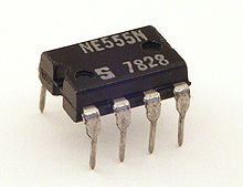
555 Timer
555 timer IC - Wikipedia - http://en.wikipedia.org/wiki/555_timer_IC
"The 555 timer IC is an integrated circuit (chip) used in a variety of timer, pulse generation, and oscillator applications. The 555 can be used to provide time delays, as an oscillator, and as a flip-flop element. Derivatives provide up to four timing circuits in one package." [1]
IC labels NE555N vs NE555P = The NE555N should be identical to the NE555P. Generally the different letters prior to, and after the 555 marking refers to different manufactures, power consumption, etc, but all 555s are generally swap-able with each other." "Generally the trailing letters in an IC part# represent variations such as package, dissipation, mil-spec, etc. For the average student or technician package is the main concern." [2]
IC Socket

Dual Inline Package DIP socket
Resistor
Ohm's law:


Resistor Sizes
http://www.resistorguide.com/resistor-sizes-and-packages/
0201 is too small to be soldered with a hand iron.
SMD Soldering - Small Packages - YouTube - https://www.youtube.com/watch?v=8Q6YNmBKjiU
SMT Component Sizes - YouTube - https://www.youtube.com/watch?v=0NrrfotuANY
Capacitor
Diode
Diode - Wikipedia - http://en.wikipedia.org/wiki/Diode
Thin bar depicts the cathode.

LED
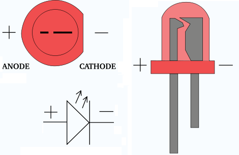
Short leg is negative (cathode), long leg is positive (anode). Flat side is negative.
Zener diode
Zener diode - Wikipedia - http://en.wikipedia.org/wiki/Zener_diode
"A Zener diode is a diode which allows current to flow in the forward direction in the same manner as an ideal diode, but will also permit it to flow in the reverse direction when the voltage is above a certain value known as the breakdown voltage, "zener knee voltage", "zener voltage" or "avalanche point"."

Relay
Electronic Switch
Relay - Wikipedia - http://en.wikipedia.org/wiki/Relay
How to use a relay | BUILD CIRCUIT - http://www.buildcircuit.com/how-to-use-a-relay/
Amazon.com: Amico 10 Pcs DC 5V Coil 7A 240VAC 10A 125VAC/28VDC 5 Pins SPST Power Relay JQC-3F: Home Improvement ($6.44 for 10 Pack) - http://www.amazon.com/Amico-240VAC-125VAC-28VDC-JQC-3F/dp/B008SO6BDK/ref=sr_1_sc_1?ie=UTF8&qid=1375627504&sr=8-1-spell&keywords=5V+relayn+SPST#productDetails
Seems to be the common term is a "Power Relay".


Transistor
Voltage Divider


Note: If both resistors are equal Ohms, then the voltage will be cut in half.
For a more accurate voltage control see #Voltage Regulator
-
"In electronics or EET, a voltage divider (also known as a potential divider) is a linear circuit that produces an output voltage (Vout) that is a fraction of its input voltage (Vin). Voltage division refers to the partitioning of a voltage among the components of the divider.
An example of a voltage divider consists of two resistors in series or a potentiometer. It is commonly used to create a reference voltage, or to get a low voltage signal proportional to the voltage to be measured, and may also be used as a signal attenuator at low frequencies. For direct current and relatively low frequencies, a voltage divider may be sufficiently accurate if made only of resistors; where frequency response over a wide range is required, (such as in an oscilloscope probe), the voltage divider may have capacitive elements added to allow compensation for load capacitance. In electric power transmission, a capacitive voltage divider is used for measurement of high voltage." (Voltage divider - Wikipedia - http://en.wikipedia.org/wiki/Voltage_divider)
-
"A voltage divider is a simple circuit which turns a large voltage into a smaller one. Using just two series resistors and an input voltage, we can create an output voltage that is a fraction of the input. Voltage dividers are one of the most fundamental circuits in electronics." (Voltage Dividers - Learn.SFE - https://learn.sparkfun.com/tutorials/voltage-dividers)
Voltage Regulator
3.3V Voltage Regulator:
- Voltage Regulator - 3.3V - SparkFun Electronics (LD1117V33) ($2) - https://www.sparkfun.com/products/526
- PMIC - Voltage Regulators - Linear (LDO) | Integrated Circuits (ICs) | DigiKey ($0.60) - http://www.digikey.com/product-search/en?WT.z_header=search_go&lang=en&site=us&keywords=LD1117V33&x=0&y=0
Logic Level Converter
Logic Level Converter - SparkFun Electronics - https://www.sparkfun.com/products/8745
- "Logic level converter is a small device that safely steps down 5V signals to 3.3V and steps up 3.3V to 5V."
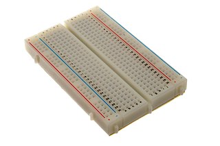
Breadboard
Breadboard - Wikipedia - http://en.wikipedia.org/wiki/Breadboard
"A breadboard (or protoboard) is usually a construction base for prototyping of electronics. The term "breadboard" is commonly used to refer to a solderless breadboard (plugboard). Because the solderless breadboard for electronics does not require soldering, it is reusable. This makes it easy to use for creating temporary prototypes and experimenting with circuit design. Older breadboard types did not have this property. A stripboard (veroboard) and similar prototyping printed circuit boards, which are used to build semi-permanent soldered prototypes or one-offs, cannot easily be reused. A variety of electronic systems may be prototyped by using breadboards, from small analog and digital circuits to complete central processing units (CPUs)."
Hook-up Wire
---
"Don't use stranded wire. (For a final version of a circuit not on a breadboard, however, stranded wire is usually better since it is less likely to break under repeated bending.)" [3]
"Most breadboards can accept wire sizes in the range 19-29 AWG, but 22 AWG is standard. The lower the AWG, the thicker the wire, just like with pasta. Thicker wire should be used for higher current." [4]
---
Home Depot:
Cerrowire 65 ft. 20/2 Bell Wire-206-0101BA3 at The Home Depot ($8) - http://www.homedepot.com/p/Cerrowire-65-ft-20-2-Bell-Wire-206-0101BA3/202304706#.UjVNwj-OA9k
---
Hook-up Wire - White - SparkFun Electronics ($3) - https://www.sparkfun.com/products/8026
- Standard 22 AWG solid White hook up wire. Use this with your bread board or any project in which you need sturdy wire. Comes in small spools of 25'.
---
"Cat 5 and Cat 5e cables typically use 24–26 AWG wire. Category 6 cable tend to have slightly more copper in each cable, with standard gauges of 22–24 AWG." [5]
---
"Here is a link to calculators that can determine the effective wire gauge of multiple strands and conductors:
In your case, two 24 gauge wires in parallel equals 21 gauge. Three would equal 19 gauge, etc. It would take an entire 4-pair CAT-5 cable to equal one 18/2 power wire. We often use one CAT-5 for video, power and PTZ control signals and have never experienced interference between functions." [6]
Perfboard
Perfboard - Wikipedia - http://en.wikipedia.org/wiki/Perfboard
Stripboard:
- "Perfboard differs from stripboard in that each pad on perfboard is isolated. Stripboard is made with rows of copper conductors that form default connections, which are broken into isolated segments as required by scraping through the copper"
TriPad Stripboard:
- "similar to stripboard, except that the conductive tracks do not run continuously along the board but are broken into sections, each of which spans three holes."
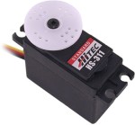
Servo
Digital vs Analog
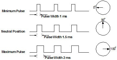
"The servo is controlled by three wires: ground, power, and control. The servo will move based on the pulses sent over the control wire, which set the angle of the actuator arm. The servo expects a pulse every 20 ms in order to gain correct information about the angle. The width of the servo pulse dictates the range of the servo's angular motion.
A servo pulse of 1.5 ms width will typically set the servo to its "neutral" position or 45°, a pulse of 1.25 ms could set it to 0° and a pulse of 1.75 ms to 90°. The physical limits and timings of the servo hardware varies between brands and models, but a general servo's angular motion will travel somewhere in the range of 90° - 120° and the neutral position is almost always at 1.5 ms. This is the "standard pulse servo mode" used by all hobby analog servos."
Servo (radio control) - Wikipedia - http://en.wikipedia.org/wiki/Servo_%28radio_control%29
-
How to Build a Robot Tutorial - Society of Robots - http://www.societyofrobots.com/actuators_servos.shtml
- Servos are DC motors with built in gearing and feedback control loop circuitry. And no motor drivers required!
Servo Wiring- All servos have three wires:
- Black or Brown is for ground.
- Red is for power (~4.8-6V).
- Yellow, Orange, or White is the signal wire (3-5V).
-
Servo Wiring Information - http://www.fatlion.com/sailplanes/servos.html
-

-
Arduino UNO Tutorial 2 - Servos - http://www.hobbytronics.co.uk/arduino-tutorial2-servos
-
Understanding RC Servos – Digital, Analog, Coreless, Brushless - http://www.rchelicopterfun.com/rc-servos.html
"Speed is a measurement of the time it takes the servo to rotate a certain number of degrees. This has been standardized in most specifications to 60 degrees; In other words, the time it takes the servo wheel to turn 60°. The smaller the number, the faster the servo is. "
Analog Servo Operation:
"An analog RC servo controls the speed of the motor by applying on and off voltage signals or pulses to the motor. This voltage is constant (the voltage of the receiver battery pack, voltage regular, or BEC to be exact - 4.8 to 6.0 volts).
This on off frequency is standardized to 50 cycles a second. The longer each on pulse is, the faster the motor turns and the more torque it produces.
This is the same way the speeds of most motors are controlled. For instance, if you have a ceiling or exhaust fan in your house that is controlled with a variable rotary dial speed switch; the fan motor is not given lower and higher voltages to adjust the speed.
The speed switch simply cycles the 120 volts to the fan motor on and off many times a second. The longer each on pulse is, the faster the fan runs. This is also the same way electronic speed controllers for electric RC helicopters , planes, cars, and boats work. "
Digital RC Servo Operation:
"Digital servos to the rescue! Like I said before, a digital servo has all the same parts as an analog servo, even the three wire plug that plugs into the receiver is the same. The difference is in how the pulsed signals are sent to the servo motor.
A small microprocessor inside the servo analyzes the receiver signals and processes these into very high frequency voltage pulses to the servo motor. Instead of 50 pulses per second, the motor will now receive upwards of 300 pulses per second. The pulses will be shorter in length of course, but with so many voltage pulses occurring, the motor will speed up much quicker and provide constant torque.
Now nothing is perfect and this increase in speed, torque, and holding power does come with a small disadvantage. Power Consumption!"
-
Continuous rotating/normal servo - all in one | Let's Make Robots! - http://letsmakerobots.com/node/24705
-
Servo Analog Out & Tone | TechnoChic blog - http://technochicblog.wordpress.com/2012/09/26/servo-analog-out-tone/
TTL
Transistor–transistor logic - Wikipedia - http://en.wikipedia.org/wiki/Transistor-transistor_logic
"Transistor–transistor logic (TTL) is a class of digital circuits built from bipolar junction transistors (BJT) and resistors. It is called transistor–transistor logic because both the logic gating function (e.g., AND) and the amplifying function are performed by transistors (contrast with RTL and DTL)."
Electronics
See Electronics
DIY Electronics
See Electronics/DIY
Schematic
See Schematic