Raspberry Pi
Raspberry Pi
Raspberry Pi - http://www.raspberrypi.org/
Power
Power is provided through a Micro USB port with a 700 mA (3.5 W) (Model B) / 300 mA (1.5 W) (Model A) requirement
RPi Hardware - eLinux.org - http://elinux.org/RPi_Hardware#Power
I highly recommend at least a 1.2A power supply (if using wireless or anything more than keyboard/mouse)!
Power Test Points
How Can I tell if the power supply is inadequate? - http://elinux.org/RPi_Hardware#Power
- "If you think you have a problem with your power supply, it is a good idea to check the actual voltage on the Raspberry Pi circuit board. Two test points labelled TP1 and TP2 are provided on the circuit board to facilitate voltage measurements.
- Use a multimeter which is set to the range 20 volts DC (or 20v =). You should see a voltage between 4.75 and 5.25 volts. Anything outside this range indicates that you have a problem with your power supply or your power cable, or the input polyfuse F3. Anything inside, but close to the limits, of this range may indicate a problem. "
Raspberry Pi - How to check your power supplys voltage - YouTube - https://www.youtube.com/watch?v=W3nH-Bh1Q0Q
- Use Multi Meter to check TP1 to TP2 Voltage. 4.75 V - 5.25 V is a valid range.
Power Consumption
"According to Kill-A-Watt meter, power consumption over 40 hours was 0.09 kWh, or 2.3 Watts per hour." [1]
"about .20 Amps at 12.5V" "Bottom line. Pi uses about 2 watts at idle." [2]
How To Tell Model
Newer versions:
$ cat /proc/device-tree/model
$ cat /sys/firmware/devicetree/base/model
Raspberry Pi 3 Model B Rev 1.2
--
cat /proc/cpuinfo | grep 'Revision' | awk '{print $3}' | sed 's/^1000//'
# or
awk '/^Revision/ {sub("^1000", "", $3); print $3}' /proc/cpuinfo
Revision	Release Date	Model		PCB Revision	Memory	Notes
Beta		Q1 2012		B (Beta)	?	256 MB	Beta Board
0002		Q1 2012		B		1.0	256 MB
0003		Q3 2012		B (ECN0001)	1.0	256 MB	Fuses mod and D14 removed
0004		Q3 2012		B		2.0	256 MB	(Mfg by Sony)
0005		Q4 2012		B		2.0	256 MB	(Mfg by Qisda)
0006		Q4 2012		B		2.0	256 MB	(Mfg by Egoman)
0007		Q1 2013		A		2.0	256 MB	(Mfg by Egoman)
0008		Q1 2013		A		2.0	256 MB	(Mfg by Sony)
0009		Q1 2013		A		2.0	256 MB	(Mfg by Qisda)
000d		Q4 2012		B		2.0	512 MB	(Mfg by Egoman)
000e		Q4 2012		B		2.0	512 MB	(Mfg by Sony)
000f		Q4 2012		B		2.0	512 MB	(Mfg by Qisda)
0010		Q3 2014		B+		1.0	512 MB	(Mfg by Sony)
0011		Q2 2014		Compute Module 1 1.0	512 MB	(Mfg by Sony)
0012		Q4 2014		A+		1.1	256 MB	(Mfg by Sony)
0013		Q1 2015		B+		1.2	512 MB	(Mfg by Embest)
0014		Q2 2014		Compute Module 1 1.0	512 MB	(Mfg by Embest)
0015		?		A+		1.1	256 MB / 512 MB	(Mfg by Embest)
a01040		Unknown		2 Model B	1.0	1 GB	(Mfg by Sony)
a01041		Q1 2015		2 Model B	1.1	1 GB	(Mfg by Sony)
a21041		Q1 2015		2 Model B	1.1	1 GB	(Mfg by Embest)
a22042		Q3 2016		2 Model B 	1.2	1 GB	(Mfg by Embest)
900021		Q3 2016		A+		1.1	512 MB	(Mfg by Sony)
900032		Q2 2016?	B+		1.2	512 MB	(Mfg by Sony)
900092		Q4 2015		Zero		1.2	512 MB	(Mfg by Sony)
900093		Q2 2016		Zero		1.3	512 MB	(Mfg by Sony)
920093		Q4 2016?	Zero		1.3	512 MB	(Mfg by Embest)
9000c1		Q1 2017		Zero W		1.1	512 MB	(Mfg by Sony)
a02082		Q1 2016		3 Model B	1.2	1 GB	(Mfg by Sony)
a020a0		Q1 2017		Compute Module 3 1.0	1 GB	(Mfg by Sony)
a22082		Q1 2016		3 Model B	1.2	1 GB	(Mfg by Embest)
a32082		Q4 2016		3 Model B	1.2	1 GB	(Mfg by Sony Japan)
a020d3		Q1 2018		3 Model B+	1.3	1 GB	(Mfg by Sony)
9020e0		Q4 2018		3 Model A+	1.0	512 MB	(Mfg by Sony)
Ref: RPi HardwareHistory - eLinux.org - https://elinux.org/RPi_HardwareHistory
Model A vs B
Model B indicates the presence of an Ethernet port. Model A indicates a lower-cost model in a smaller form factor with no Ethernet port, reduced RAM, and fewer USB ports to limit board height.
Raspberry Pi product series explained - Raspberry Pi
https://www.raspberrypi.com/news/raspberry-pi-product-series-explained/
Model B includes additionally the following:
- 512 MB RAM (vs 256 MB RAM)
- 2 USB ports (vs 1)
- Ethernet
- Higher power requirement of 700 mA (vs 300 mA)
Model B Rev 1 vs Rev 2
How do you find out if you have a rev 1 or 2 board? Is it worth upgrading? [3]
- The rev 2 boards have 2 mounting holes drilled through the board. The rev 1 boards dont have any mounting holes. That's the basic visual check you can perform to check which version you have
Model B Rev 1 came in only 256 MB of RAM. Model B Rev 2 comes in both 256 MB and 512 MB. If you have 512 MB of RAM, it is a Rev 2 board!
Model B Rev 2 Board:
# grep Revision /proc/cpuinfo
Revision        : 000e
Model B Rev 2 (HW Rev 000e): Rev2 Model B, 512MB RAM, Ethernet, two USB sockets, five LEDs, mounting holes, Pin3=GPIO1, Pin5=GPIO2, Pin13=GPIO27, 12C-1, 8 extra IO pads (P5) [4]
Full output of a Model B Rev 2 Board
# cat /proc/cpuinfo
Processor       : ARMv6-compatible processor rev 7 (v6l)
BogoMIPS        : 697.95
Features        : swp half thumb fastmult vfp edsp java tls
CPU implementer : 0x41
CPU architecture: 7
CPU variant     : 0x0
CPU part        : 0xb76
CPU revision    : 7

Hardware        : BCM2708
Revision        : 000e
Serial          : 00000000b4ae7143
References:
- Raspberry Pi • View topic - Raspbarry Pi Model B Rev 1 or 2 - http://www.raspberrypi.org/phpBB3/viewtopic.php?f=26&t=25479
- Upcoming board revision | Raspberry Pi - http://www.raspberrypi.org/archives/1929
- Automatic Raspberry Pi board revision detection: model A, B1 and B2 | Raspberry Alpha Omega - http://raspberryalphaomega.org.uk/2013/02/06/automatic-raspberry-pi-board-revision-detection-model-a-b1-and-b2/
Purchase
Amazon:
- Amazon.com: Raspberry Pi Model B Revision 2.0 (512MB): Electronics ($43) - http://amzn.com/B009SQQF9C
- Amazon.com: Raspberry Pi Model A (256MB): Computers & Accessories ($33) - http://amzn.com/B00BC0ZL88
Spark Fun:
- Raspberry Pi - Model B - SparkFun Electronics ($40 + $4) - https://www.sparkfun.com/products/11546
- Raspberry Pi - Model A - SparkFun Electronics ($30 + $4) - https://www.sparkfun.com/products/11837
Group: Raspberry Pi - element14 - http://www.element14.com/community/groups/raspberry-pi
- RASPBERRY-MODA-256M - RASPBERRY-PI - MODEL A - ASSEMBLED BOARD ONLY | Newark - http://www.newark.com/raspberry-pi/raspberry-moda-256m/model-a-assembled-board-only/dp/56W4050?COM=raspi-group
- RASPBRRY-MODB-512M - RASPBERRY-PI - MODEL B - ASSEMBLED BOARD ONLY | Newark - http://www.newark.com/jsp/search/productdetail.jsp?sku=43W5302&COM=raspi-group
Here are a few places to try that often have a few in stock: [5]
- Adafruit (the kit is almost always in stock if the singular unit isn't)
- Amazon (almost always in stock, but through third parties at a premium)
- Allied Electronics (only available in North America)
GPIO

RPi Low-level peripherals - eLinux.org - http://elinux.org/RPi_Low-level_peripherals
"In addition to the familiar USB, Ethernet and HDMI ports, the R-Pi offers lower-level interfaces intended to connect more directly with chips and subsystem modules. These GPIO (general purpose I/O) signals on the 2x13 header pins include SPI, I2C, serial UART, 3V3 and 5V power. These interfaces are not "plug and play" and require care to avoid miswiring. The pins use a 3V3 logic level and are not tolerant of 5V levels, such as you might find on a 5V powered Arduino. CSI (camera serial interface) can be used to connect the 5 MP camera available. Not yet software-enabled is the flex cable connectors with DSI (display serial interface) and a serial link inside the HDMI connector called CEC. (consumer electronics control) "
-

"General Purpose Input/Output (a.k.a. GPIO) is a generic pin on a chip whose behavior (including whether it is an input or output pin) can be controlled (programmed) through software. " [6]
GPIO Installation
apt-get install pigpio raspi-gpio wiringpi
lsmod | grep -i gpio
# modprobe gpio
modprobe bcm2835_gpiomem
Command Line
gpio readall
gpio mode [pin] [mode]  # mode = in or out
gpio read [pin]  # returns: 0 or 1
gpio write [pin] [value]  # value = 0 or 1
Programming
http://elinux.org/RPi_Low-level_peripherals
import RPi.GPIO as GPIO

# use P1 header pin numbering convention
GPIO.setmode(GPIO.BOARD)

# Set up the GPIO channels - one input and one output
GPIO.setup(11, GPIO.IN)
GPIO.setup(12, GPIO.OUT)

# Input from pin 11
input_value = GPIO.input(11)

# Output to pin 12
GPIO.output(12, GPIO.HIGH)

# The same script as above but using BCM GPIO 00..nn numbers
GPIO.setmode(GPIO.BCM)
GPIO.setup(17, GPIO.IN)
GPIO.setup(18, GPIO.OUT)
input_value = GPIO.input(17)
GPIO.output(18, GPIO.HIGH)

GPIO.cleanup()
Output
import time
import RPi.GPIO as GPIO
GPIO.setmode(GPIO.BCM)
try:
  GPIO.setup(18, GPIO.OUT)
  GPIO.output(18, GPIO.HIGH)
  time.sleep(1)
  GPIO.output(18, GPIO.LOW)
finally:
  GPIO.cleanup()
Input
#!/usr/bin/env python

import sys
import time

import RPi.GPIO as GPIO

pin = 25

GPIO.setmode(GPIO.BCM)
GPIO.setup(pin, GPIO.IN)

try:
  while True:
    input_value = GPIO.input(pin)
    if input_value:
      sys.stdout.write('-')
    else:
      sys.stdout.write('.')
    sys.stdout.flush()
    time.sleep(.01)
finally:
  GPIO.cleanup()
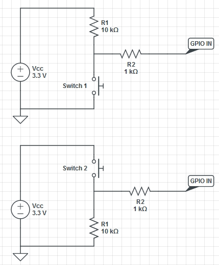
- Pull Up (top) - default High
- Pull Down (bottom) - default Low
"When a GPIO pin is set as an input it is “floating” and has no defined voltage level. For us to be able to reliably detect whether the input is high or low we need to tie it so that it is always connected and either reads high or low.
To tie the pin we connect either a Pull Up or Pull Down resistor. A Pull down resistor connects the pin to ground through a large resistor, this means that when the switch is open there is a path to ground and so it will read low. When the switch is pressed (with the other side connected to 3.3V) there is a lower resistance path to high and so the pin will read high. The large (10kΩ) resistor ensures that only a little current is drawn when the switch is pressed.
Setting up a circuit like this means that we will be able to take reliable readings from a switch, however we could still damage the pins if they are accidentally set to an output. If we drive it low the output is connected directly to ground. Pushing the button will then create a short circuit between 3.3V and ground! To make this safer we put in a current limiting resistor (1kΩ will do) to make sure the Pi can handle the current drawn." (Buttons and Switches - Physical Computing with Raspberry Pi)
References:
- Buttons and Switches - Physical Computing with Raspberry Pi - http://www.cl.cam.ac.uk/projects/raspberrypi/tutorials/robot/buttons_and_switches/
--
Inputs - raspberry-gpio-python - How to use inputs in RPi.GPIO - Python library for GPIO access on a Raspberry Pi - Google Project Hosting - http://code.google.com/p/raspberry-gpio-python/wiki/Inputs
Pull up / Pull down resistors
GPIO.setup(channel, GPIO.IN, pull_up_down=GPIO.PUD_UP)
GPIO.setup(channel, GPIO.IN, pull_up_down=GPIO.PUD_DOWN)
while GPIO.input(channel) == GPIO.LOW:
   time.sleep(0.01)  # wait 10 ms to give CPU chance to do other things
-
Overview | Adafruit's Raspberry Pi Lesson 4. GPIO Setup | Adafruit Learning System - http://learn.adafruit.com/adafruits-raspberry-pi-lesson-4-gpio-setup/overview
"One of the great things about the Raspberry Pi is that it has a GPIO connector to which you can attach external hardware."
-
GPIO Electrical Specifications, Raspberry Pi Input and Output Pin Voltage and Current Capability - http://www.mosaic-industries.com/embedded-systems/microcontroller-projects/raspberry-pi/gpio-pin-electrical-specifications
-
Computer Laboratory – Raspberry Pi: Section 2: GPIO - http://www.cl.cam.ac.uk/projects/raspberrypi/tutorials/turing-machine/two.html
-
YouTube Video
What are the input voltage thresholds for the Raspberry Pi's GPIO pins? - YouTube - http://www.youtube.com/watch?v=Wr49ia3oID4
LOW: 0V - 1.19V
HIGH: 1.34V - 3.30V
Cute Qubit Online - http://cutequbit.zapto.org/
GPIO Interrupts
Check if your version of Python GPIO library has support:
sudo python
import RPi.GPIO as GPIO
GPIO.VERSION
# need 0.5.1 or higher
Check for falling edge:
#!/usr/bin/env python

import sys
import time

import RPi.GPIO as GPIO

GPIO.setmode(GPIO.BCM)
GPIO.setup(25, GPIO.IN)

try:
  while True:
    # RISING, FALLING or BOTH
    GPIO.wait_for_edge(25, GPIO.FALLING)
    print "Change detected"
finally:
  GPIO.cleanup()
Interrupts and Edge detection - To avoid missing a button press while your program is busy doing something else, there are two ways to get round this:
- the wait_for_edge() function
- the event_detected() function
- a threaded callback function that is run when an edge is detected
wait_for_edge() function:
GPIO.wait_for_edge(channel, GPIO.RISING)
event_detected() function
GPIO.add_event_detect(channel, GPIO.RISING)  # add rising edge detection on a channel
do_something()
if GPIO.event_detected(channel):
    print('Button pressed')
# remove event, if needed
GPIO.remove_event_detect(channel)
Threaded callbacks:
def my_callback(channel):
  ...

GPIO.add_event_detect(channel, GPIO.RISING, callback=my_callback)
References:
- How to use interrupts with Python on the Raspberry Pi and RPi.GPIO » RasPi.TV - http://raspi.tv/2013/how-to-use-interrupts-with-python-on-the-raspberry-pi-and-rpi-gpio
- How to use interrupts with Python on the Raspberry Pi and RPi.GPIO – part 2 » RasPi.TV - http://raspi.tv/2013/how-to-use-interrupts-with-python-on-the-raspberry-pi-and-rpi-gpio-part-2
- How to use interrupts with Python on the Raspberry Pi and RPi.GPIO – part 3 » RasPi.TV - http://raspi.tv/2013/how-to-use-interrupts-with-python-on-the-raspberry-pi-and-rpi-gpio-part-3
- Inputs - raspberry-gpio-python - How to use inputs in RPi.GPIO - Python library for GPIO access on a Raspberry Pi - Google Project Hosting - http://code.google.com/p/raspberry-gpio-python/wiki/Inputs
---
MagPi - Interrupt Test23 - http://ryniker.ods.org/raspberrypi/MagPi/interrupt_test23.py
MagPi - GPIO Interrupts - http://ryniker.ods.org/raspberrypi/MagPi/GPIO_interrupts
#!/usr/bin/python3

# Test interrupts.

import select, time, sys

pin_base = '/sys/class/gpio/gpio23/'

def write_once(path, value):
    f = open(path, 'w')
    f.write(value)
    f.close()
    return


f = open(pin_base + 'value', 'r')

write_once(pin_base + 'direction', 'in')
write_once(pin_base + 'edge', 'both')

po = select.poll()
po.register(f, select.POLLPRI)

state_last = f.read(1)
t1 = time.time()
sys.stdout.write('Initial pin value = {}\n'.format(repr(state_last)))

while 1:
    events = po.poll(60000)
    t2 = time.time()
    f.seek(0)
    state_last = f.read(1)
    if len(events) == 0:
        sys.stdout.write('  timeout  delta = {:8.4f} seconds\n'.format(t2 - t1))
    else:
        sys.stdout.write('value = {}  delta ={:8.4f}\n'.format(state_last, t2 - t1))
        t1 = t2
GPIO Permissions
MagPi - gpio_control.c - http://ryniker.ods.org/raspberrypi/MagPi/gpio_control.c
Switch debounce
You may notice that the callbacks are called more than once for each button press. This is as a result of what is known as 'switch bounce'. There are two ways of dealing with switch bounce:
- add a 0.1uF capacitor across your switch.
- software debouncing
- a combination of both
GPIO Boot State
"The RPi is not setting the GPIO to output when first booted. It is turning on a pull down resistor for 740 milliseconds. I have used two 18K resistors ( 3v3 -> GPIO -> GND ) to look at exactly what is going on with the pins. Here is the trace. Blue line is 3v3 power, yellow line is GPIO line." [7]
- boot - What is the power on state of the GPIOs? - Raspberry Pi Stack Exchange - http://raspberrypi.stackexchange.com/questions/1032/what-is-the-power-on-state-of-the-gpios
- Raspberry Pi • View topic - Power on behaviour - http://www.raspberrypi.org/phpBB3/viewtopic.php?t=7443&p=93865
-
"All the GPIO pins can be reconfigured to provide alternate functions, SPI, PWM, I²C and so. At reset only pins GPIO 14 & 15 are assigned to the alternate function UART, these two can be switched back to GPIO to provide a total of 17 GPIO pins[3]. Each of their functions and full details of how to access are detailed in the chipset datasheet."
So don't use GPIO 14 & 15 for sensitive tasks. (14 specifically has boot issues!)
RPi Low-level peripherals - eLinux.org - http://elinux.org/RPi_Low-level_peripherals
-
"I know you want to avoid resistors on the GPIO pins, but I don't know any other way around the issue, as most pins are inputs and are floating. I use a 10k resistor from each GPIO I am using to ground, before my other circuitry. By choosing the proper pins (Pins where MODE=IN and VALUE=LOW at boot. See the chart labeled "Rev 2 pin state at boot time" at the url below) and by adding the resistors, you are guaranteed a LOW at boot, and still are able to set the pins to a LOW or HIGH in software." - Raspberry Pi • View topic - GPIO random voltage upon boot - http://www.raspberrypi.org/phpBB3/viewtopic.php?f=26&t=47895
See also: - Raspberry Pi • View topic - GPIO Pin States a Boot time - Change in 3.6.11+ - http://www.raspberrypi.org/phpBB3/viewtopic.php?f=44&t=35321
<pre>
Rev 2 pin state at boot time:
+----------+-Rev2-+------+--------+------+-------+
| wiringPi | GPIO | Phys | Name   | Mode | Value |
+----------+------+------+--------+------+-------+
|      0   |  17  |  11  | GPIO 0 | IN   | Low   |
|      1   |  18  |  12  | GPIO 1 | IN   | Low   |
|      2   |  27  |  13  | GPIO 2 | IN   | Low   |
|      3   |  22  |  15  | GPIO 3 | IN   | Low   |
|      4   |  23  |  16  | GPIO 4 | IN   | Low   |
|      5   |  24  |  18  | GPIO 5 | IN   | Low   |
|      6   |  25  |  22  | GPIO 6 | IN   | Low   |
|      7   |   4  |   7  | GPIO 7 | IN   | Low   |
|      8   |   2  |   3  | SDA    | IN   | High  |
|      9   |   3  |   5  | SCL    | IN   | High  |
|     10   |   8  |  24  | CE0    | IN   | Low   |
|     11   |   7  |  26  | CE1    | IN   | Low   |
|     12   |  10  |  19  | MOSI   | IN   | Low   |
|     13   |   9  |  21  | MISO   | IN   | Low   |
|     14   |  11  |  23  | SCLK   | IN   | Low   |
|     15   |  14  |   8  | TxD    | ALT0 | High  |
|     16   |  15  |  10  | RxD    | ALT0 | High  |
|     17   |  28  |   3  | GPIO 8 | IN   | Low   |
|     18   |  29  |   4  | GPIO 9 | IN   | Low   |
|     19   |  30  |   5  | GPIO10 | IN   | Low   |
|     20   |  31  |   6  | GPIO11 | IN   | Low   |
+----------+------+------+--------+------+-------+
Onboard LED
Only the Green is controllable:
# off
echo 0 >/sys/class/leds/led0/brightness
# on
echo 1 >/sys/class/leds/led0/brightness
while true ; do echo 0 >/sys/class/leds/led0/brightness ; sleep .5 ;
echo 1 >/sys/class/leds/led0/brightness ; sleep .5 ; done
Blink the light (by me): (/usr/local/sbin/blink)
#!/bin/bash
echo "Blinking..."
trap "{ echo Exiting ; echo 0 >/sys/class/leds/led0/brightness ; exit 0 ; }" SIGINT SIGTERM
while true ; do
  echo -n "."
  # on
  echo 1 >/sys/class/leds/led0/brightness
  sleep .1
  # off
  echo 0 >/sys/class/leds/led0/brightness
  sleep .1
done
References:
- Raspberry Pi • View topic - Can we control the on-board leds - http://www.raspberrypi.org/phpBB3/viewtopic.php?f=31&t=12530
IP Address
Add to /etc/rc.local: [8]
_IP=$(hostname -I) || true
if [ "$_IP" ]; then
  printf "My IP address is %s\n" "$_IP"
  espeak "Welcome to Rasberry pi. My I.P. is $_IP. I repeat: $_IP"
else
  espeak "Welcome to Rasberry pi. No I.P. found."
fi
Onboard Audio and Sound
Setup device
lsmod | grep snd_bcm2835 # verify audio module loaded
Set device:
amixer info  # show devices
amixer controls  # show controls
  numid=2,iface=MIXER,name='Headphone Playback Switch'
  numid=1,iface=MIXER,name='Headphone Playback Volume'
#amixer cset numid=3 1  # force analog 3.5mm jack -- doesn't work?
amixer cset numid=3 1  # force analog 3.5mm jack -- doesn't work?
Set Volume:
# depending on device...
amixer   # show devices
amixer set PCM 80%  # set PCM volume to 80%
amixer set Headphone  # get values
amixer set Headphone 80%  # set Headphonevolume to 80%
amixer controls  # show controls
amixer cget name='Headphone Playback Volume'
   numid=1,iface=MIXER,name='Headphone Playback Volume'
     ; type=INTEGER,access=rw---R--,values=1,min=-10239,max=400,step=0
     : values=-1727
     | dBscale-min=-102.39dB,step=0.01dB,mute=1
amixer cset name='Headphone Playback Volume' 400  # set to max volume in db scale
Shell WAV:
wget http://www.freespecialeffects.co.uk/soundfx/sirens/police_s.wav
aplay police_s.wav
Shell MP3: (not amixer volume does affect this)
sudo apt-get -y install mpg321
wget http://www.freespecialeffects.co.uk/soundfx/household/bubbling_water_1.mp3
mpg321 bubbling_water_1.mp3
mpg321 -g 50 bubbling_water_1.mp3  # 50% volume (default is 100%)
Python MP3: [9]
import pygame
pygame.mixer.init()
pygame.mixer.music.load("myFile.wav")
pygame.mixer.music.play()
Text to audio:
apt-get install espeak
espeak "hello world"
espeak "hello world" 2> /dev/null
speak "someone going out the garage" -a 200 -p 20 -s 80
Quantum Bits » Project “Jarvis”: step two (speak to me) - [10]
""" /usr/bin/curl -A "Mozilla"
"http://translate.google.com/translate_tts?tl=en_gb&ie="UTF-8"&q='{msg}' > google.mp3 """.format(msg=msg)
References:
- Raspberry Pi Command Line Audio | Raspberry Pi Spy - http://www.raspberrypi-spy.co.uk/2013/06/raspberry-pi-command-line-audio/
- Playing sounds and using buttons with Raspberry Pi | Adafruit Learning System - http://learn.adafruit.com/playing-sounds-and-using-buttons-with-raspberry-pi/
- Quantum Bits » Project “Jarvis”: step two (speak to me) - http://quantum-bits.org/?p=614
- amixer command in Linux with Examples - GeeksforGeeks - https://www.geeksforgeeks.org/amixer-command-in-linux-with-examples/
Google Text to Speech
Google TTS - "Google Text-To-Speech is a private REST API. Getting results is less straightforward but noneless very easily manageable."
Get Google TTS through Python: (modified from [11])
cmd = """ /usr/bin/curl -A "Mozilla"
  "http://translate.google.com/translate_tts?tl=en_gb&ie="UTF-8"&q='{msg}' > google.mp3 """.format(msg=msg)
os.system(cmd)
References:
- Quantum Bits » Project “Jarvis”: step two (speak to me) - http://quantum-bits.org/?p=614
- The Unofficial Google Text-To-Speech API | TechCrunch - http://techcrunch.com/2009/12/14/the-unofficial-google-text-to-speech-api/
Raspbian Installation
Raspbian Download - http://www.raspberrypi.org/downloads/
Write image to SD card:
wget http://downloads.raspberrypi.org/raspbian_latest
unzip 2014-01-07-wheezy-raspbian.zip
sudo dd if=2014-01-07-wheezy-raspbian.img of=/dev/sdh bs=1M
Win32 Disk Imager | SourceForge.net - http://sourceforge.net/projects/win32diskimager/
- Win32DiskImager-0.9.5-install.exe (installer) or Win32DiskImager-0.9.5-binary.zip (binary)
Note: Ethernet with SSHD configured on by default
Boot Raspberry Pi and Configure:
## Login: pi : raspberry
sudo su -


## Configure Raspberry Pi
##    auto runs the first time you sudo to root, and it will reboot the Pi
raspi-config
# - Expand Filesystem
# - Change User Password (Optional)
# - Internaltionalisation Options - Change Locale - (uncheck "en_GB.UTF-8 UTF-8", check "en_US.*" (x3), and set "en_US.UTF-8" as default)
# - Internaltionalisation Options - Change Timezone - US - Mountain
# - Advanced Options - Hostname
# - Advanced Options - Memory Split - Set to 16 (for server) or 128 (for picamera)
# - Advanced Options - Update

reboot
# --- REBOOT --- #
# --- REBOOT --- #
# --- REBOOT --- #


sudo su -

passwd   # change root password


hostname [HOSTNAME]
hostname > /etc/hostname
# echo "[HOSTNAME]" > /etc/hostname
# hostname [HOSTNAME]
# hostname `cat /etc/hostname`
cat /etc/hostname
hostname HOSTNAME
echo $HOSTNAME > /etc/hostname


# Apply pseudo random number to change default hostid from '007f0101',
#   which is based on /etc/hosts entries
hostid
hostid > /etc/hostid.old
#echo $RANDOM > /etc/hostid
wget http://piregister.oeey.com/sethostid.txt -O /usr/local/sbin/sethostid
chmod u+x /usr/local/sbin/sethostid
sethostid
hostid

# set timezone
mv /etc/localtime /etc/localtime.original
ln -s /usr/share/zoneinfo/America/Denver /etc/localtime
date

#cp /etc/profile /etc/profile.original
#echo "" >> /etc/profile
#echo "export EDITOR=vim" >> /etc/profile
#export EDITOR=vim

cp ~/.bashrc ~/.bashrc.original
echo "" >> ~/.bashrc
echo "export EDITOR=vim" >> ~/.bashrc
export EDITOR=vim
echo "alias ls='ls --color'" >> ~/.bashrc
alias ls='ls --color'

apt-get update
apt-get -y install vim screen espeak mpg321 mercurial tree python-pip rsync wiringpi
apt-get -y upgrade

adduser kenneth  # this will also set the password
# --- PASSWORD --- #
# --- PASSWORD --- #
# --- PASSWORD --- #

# passwd kenneth  # set password
#visudo  # add to visudo
#  kenneth ALL=(ALL) NOPASSWD: ALL
# --- VISUDO --- #
# --- VISUDO --- #
# --- VISUDO --- #
echo "kenneth ALL=(ALL) NOPASSWD: ALL" >> /etc/sudoers

cp /etc/motd /etc/motd.original
> /etc/motd


wget http://piregister.oeey.com/piserial.txt -O /usr/local/bin/piserial
chmod +x /usr/local/bin/piserial
piserial

wget http://piregister.oeey.com/piregister.txt -O /usr/local/bin/piregister
chmod +x /usr/local/bin/piregister
piregister

wget http://piregister.oeey.com/blink.txt -O /usr/local/sbin/blink
chmod +x /usr/local/sbin/blink
# blink


## ADD TO CRON:
echo "# m h  dom mon dow   command" > tmpcron
echo "@reboot   /usr/local/bin/piregister" >> tmpcron
echo "0 0 * * *   /usr/local/bin/piregister" >> tmpcron
#echo "*/10 * * * *  /usr/bin/logger -- \"-- MARK --\"" >> tmpcron
echo "0 * * * *  /usr/bin/logger -- \"-- MARK --\"" >> tmpcron
crontab tmpcron
# will be added as: /var/spool/cron/crontabs/root
rm -f tmpcron


#cp /etc/rc.local /etc/rc.local.original
#sed -i '/exit 0/d' /etc/rc.local
#echo "" >> /etc/rc.local
#echo "/usr/local/bin/piregister" >> /etc/rc.local
#echo "" >> /etc/rc.local
#echo "exit 0" >> /etc/rc.local


## WIRELESS (Optional)
cat > /etc/wpa_supplicant/wpa_supplicant.conf << "EOF"
ctrl_interface=DIR=/var/run/wpa_supplicant GROUP=netdev
update_config=1
# reading passphrase from stdin
network={
        ssid="toast"
        #psk="xxx"
        psk=8085
}
EOF
# ifdown --force wlan0
# ifup wlan0


# NFS
service rpcbind restart
update-rc.d rpcbind defaults
echo "prime:/pub      /pub            nfs     noauto        0 0" >> /etc/fstab
mkdir /pub
mount /pub


reboot
# --- REBOOT --- #
# --- REBOOT --- #
# --- REBOOT --- #


# Wireless should now be running


# SSH Key
ssh-keygen
# [enter] [enter] [enter]
ssh-copy-id kiloforce@oeey.com
ssh kiloforce@oeey.com 'pwd'

# Mercurial
# apt-get install mercurial
#hg clone ssh://kiloforce@oeey.com//opt/hg/pi /opt/pi-hg
#ln -sfn /opt/pi-hg /opt/hg
hg clone ssh://kiloforce@oeey.com//opt/hg/pi /opt/hg
ln -sfn /opt/pi-hg /hg
hg --cwd /opt/hg pull -u

#ln -sfn /opt/hg/common/vimrc /root/.vimrc
#ln -sfn /opt/hg/common/hgrc /root/.hgrc
#ln -sfn /opt/hg/common/piregister /usr/local/bin/piregister
#ln -sfn /opt/hg/common/piserial /usr/local/bin/piserial

cd /opt/hg
./rebuild common

./rebuild `hostname`

# System update
#apt-get update
#apt-get -y upgrade
#apt-get update ; apt-get -y upgrade ; apt-get -y dist-upgrade
apt-get update ; apt-get -y upgrade ; apt-get -y autoremove ; apt-get clean all

# reboot
reboot
RaspBMC Installation
Write image to SD card:
wget http://downloads.raspberrypi.org/raspbmc_latest
gzip -d raspbmc-2013-10-02.img.gz
sudo dd if=raspbmc-2013-10-02.img of=/dev/sdh bs=1M
Note: Ethernet with SSHD configured on by default
Boot Raspberry Pi
## WAIT FOREVER - it will go through several reboots and upgrades
## This will take a while...
Configure Raspberry Pi:
## Login: pi : raspberry
## INITIAL CONFIGURATION WILL PROCEED ON FIRST CONNECTION
## * Locale - en_US
## * Time - America / Mountain
## System will now reboot

sudo su -

## All of the expand filesystem, and other settings are done during the initial setup

passwd   # change root password


## Set hostname
hostname pi-wii
echo `hostname` > /etc/hostname


## RESTART SYSLOG
/etc/init.d/rsyslog restart


## This will take a while...
apt-get update
apt-get -y install vim screen espeak mpg321 curl alsa-utils wireless-tools wpasupplicant
apt-get autoremove


## Verify sound
wget http://www.freespecialeffects.co.uk/soundfx/sirens/police_s.wav
aplay police_s.wav
wget http://www.freespecialeffects.co.uk/soundfx/household/bubbling_water_1.mp3
mpg321 bubbling_water_1.mp3


# SETUP DEFAULT EDITOR
echo "" >> /etc/profile
echo "export EDITOR=vim" >> /etc/profile
export EDITOR=vim


adduser kenneth  # this will also set the password
# --- PASSWORD --- #
# --- PASSWORD --- #
# --- PASSWORD --- #


# passwd kenneth  # set password
visudo  # add to visudo  (note: need vim as EDITOR has been set)
  # --- VISUDO --- #
  # --- VISUDO --- #
  # --- VISUDO --- #
  kenneth ALL=(ALL) NOPASSWD: ALL


## clear message of the day
> /etc/motd


cat > /usr/local/bin/piserial << "EOF"
#!/bin/bash
cat /proc/cpuinfo | grep Serial | awk '{print $3'}
EOF
chmod +x /usr/local/bin/piserial
# test
piserial


cat > /usr/local/bin/piregister << "EOF"
#!/bin/bash
# cron: 0 0 * * *   /usr/local/bin/piregister
_IP=$(hostname -I | awk '{print $1}') || true
if [ "$_IP" ]; then
  printf "My IP address is %s\n" "$_IP"
  HOSTNAME=`hostname`
  SERIAL=`/usr/local/bin/piserial`
  /usr/bin/curl http://pi.oeey.com/register/$SERIAL/$HOSTNAME/$_IP
  logger "Registered as http://pi.oeey.com/register/$SERIAL/$HOSTNAME/$_IP"
  #espeak "Welcome to Rasberry pi. My I.P. is $_IP. I repeat: $_IP"
  logger "Welcome to Rasberry pi. My I.P. is $_IP. I repeat: $_IP"
else
  #espeak "Welcome to Rasberry pi. No I.P. found."
  logger "Welcome to Rasberry pi. No I.P. found."
fi
EOF
chmod +x /usr/local/bin/piregister
# test
piregister


## ADD TO CRON:
echo "# m h  dom mon dow   command" > tmpcron
echo "0 0 * * *   /usr/local/bin/piregister" >> tmpcron
echo "*/10 * * * *  /usr/bin/logger -- \"-- MARK -- `date`\"" >> tmpcron
crontab tmpcron
rm -f tmpcron


## ADD TO BOOT
sed -i '/exit 0/d' /etc/rc.local
echo "" >> /etc/rc.local
echo "/usr/local/bin/piregister" >> /etc/rc.local
echo "" >> /etc/rc.local
echo "exit 0" >> /etc/rc.local


## Wireless: http://wireless.kernel.org/en/users/Documentation/iw
cat > /etc/wpa_supplicant/wpa_supplicant.conf << "EOF"
#ctrl_interface=DIR=/var/run/wpa_supplicant GROUP=netdev
update_config=1
# reading passphrase from stdin
network={
        ssid="toast"
        #psk="MYPASSWORD"
        psk=8085564ae7b7ebaf397eb5eebfe5a1ec093f8b78aa00fadb9cf7f810742bba55
}
EOF

cp /etc/wpa_supplicant/functions.sh /etc/wpa_supplicant/functions.sh.bak
sed -i 's/nl80211,//g' /etc/wpa_supplicant/functions.sh

cat >> /etc/network/interfaces << "EOF"
auto wlan0
iface wlan0 inet dhcp
pre-up wpa_supplicant -D wext -i wlan0 -c /etc/wpa_supplicant/wpa_supplicant.conf -B
post-down killall -q wpa_supplicant
EOF
# /sbin/wpa_supplicant -u -s -O /var/run/wpa_supplicant
# -u enable dbus,  -s log to syslog,  -O override ctrl_interface,  -B daemon,  -D driver,  -i interface

## ADD TO BOOT
sed -i '/exit 0/d' /etc/rc.local
echo "" >> /etc/rc.local
echo "/sbin/wpa_supplicant -D wext -i wlan0 -c /etc/wpa_supplicant/wpa_supplicant.conf -B" >> /etc/rc.local
echo "" >> /etc/rc.local
echo "exit 0" >> /etc/rc.local

ifdown --force wlan0
rm -f /var/run/wpa_supplicant/wlan0
modprobe -r 8192cu
#killall wpa_supplicant
for i in `pidof wpa_supplicant` ; do kill $i ; done
# wait a second

modprobe 8192cu
#ifup wlan0

for i in `pidof wpa_supplicant` ; do kill $i ; done ; /sbin/wpa_supplicant -D wext -i wlan0 \
   -c /etc/wpa_supplicant/wpa_supplicant.conf -B

iwconfig
iwlist wlan0 scan
iwconfig wlan0 mode Managed
iwconfig wlan0 essid toast


# NFS
service rpcbind restart
update-rc.d rpcbind defaults
echo "prime:/pub      /pub            nfs     defaults        0 0" >> /etc/fstab
mkdir /pub
mount /pub


reboot
# --- REBOOT --- #
# --- REBOOT --- #
# --- REBOOT --- #


# Wireless should now be running
References:
- Turn a Raspberry Pi Into an XBMC Media Center in Under 30 Minutes - http://lifehacker.com/5929913/build-a-xbmc-media-center-with-a-35-raspberry-pi
- Raspberry Pi • View topic - Raspberry Pi Netcomm np910n WiFi Setup - http://www.raspberrypi.org/phpBB3/viewtopic.php?f=26&t=27201
OpenELEC Installation
OpenELEC Mediacenter - http://openelec.tv/
OpenELEC Download - http://openelec.tv/get-openelec/download
Installing OpenELEC on Raspberry Pi - OpenELEC - http://wiki.openelec.tv/index.php?title=Installing_OpenELEC_on_Raspberry_Pi
- Referenced from: OpenELEC Installation instructions - http://wiki.openelec.tv/index.php?title=Installation
Downloads:
- OpenELEC Mediacenter - http://openelec.tv/ (newer downloads)
- Raspberry Pi Downloads - http://www.raspberrypi.org/downloads
Write image to SD card:
yum install dosfstools e4fsprogs

wget http://openelec.tv/get-openelec/download/finish/10-raspberry-pi-builds/\
260-openelec-stable-raspberry-pi-arm -O OpenELEC-RPi.arm-3.2.4.tar
tar -xvf OpenELEC-RPi.arm-3.2.4.tar
cd OpenELEC-RPi.arm-3.2.4/
sudo ./create_sdcard /dev/sdh
sync
Patch:
--- create_sdcard  2013-12-02 00:01:00.000000000 -0700
+++ create_sdcard  2013-12-02 00:02:00.000000000 -0700
@@ -207,6 +207,7 @@
 # tell kernel we have a new partition table
   echo "telling kernel we have a new partition table..."
   partprobe "$DISK"
+  echo -n "waiting" ; while [ ! -e "$PART1" ] ; do sleep 1 ; echo -n . ; done ; echo

 # create filesystem
   echo "creating filesystem on $PART1..."
patch -p0 < patch
Tag line: OpenELEC - The living room PC for everyone
WARNING: SSH NOT enabled by default (enable with the initial wizard)
username: root
password: openelec
SSH:
 There is no working 'passwd'.

 The 'passwd' command changes passwords for user accounts.

 With OpenELEC it is not possible to change the system password

 SSH is included only as a last support resort. SSH is off by default.
 Most users never need SSH and need help using it so we need a default
 password. If you need to keep SSH always on then this is unsupported
 but can be secured with certificates.

 TIP: disable password authentication in ssh and use public key authentication.
cd /storage
mkdir pub
mount prime:/pub /storage/pub
----------------------------
----------------------------
----------------------------
Boot Raspberry Pi
## WAIT FOREVER - it will go through several reboots and upgrades
## This will take a while...
Configure Raspberry Pi:
## Login: pi : raspberry
## INITIAL CONFIGURATION WILL PROCEED ON FIRST CONNECTION
## * Locale - en_US
## * Time - America / Mountain
## System will now reboot

sudo su -

## All of the expand filesystem, and other settings are done during the initial setup

passwd   # change root password (eg. Password1)


## Set hostname
hostname pi-wii
echo `hostname` > /etc/hostname


## RESTART SYSLOG
/etc/init.d/rsyslog restart


## This will take a while...
apt-get update
apt-get -y install vim screen espeak mpg321 curl alsa-utils wireless-tools wpasupplicant
apt-get autoremove


## Verify sound
wget http://www.freespecialeffects.co.uk/soundfx/sirens/police_s.wav
aplay police_s.wav
wget http://www.freespecialeffects.co.uk/soundfx/household/bubbling_water_1.mp3
mpg321 bubbling_water_1.mp3


# SETUP DEFAULT EDITOR
echo "" >> /etc/profile
echo "export EDITOR=vim" >> /etc/profile
export EDITOR=vim


adduser kenneth  # this will also set the password
# --- PASSWORD --- #
# --- PASSWORD --- #
# --- PASSWORD --- #


# passwd kenneth  # set password
visudo  # add to visudo  (note: need vim as EDITOR has been set)
  # --- VISUDO --- #
  # --- VISUDO --- #
  # --- VISUDO --- #
  kenneth ALL=(ALL) NOPASSWD: ALL


## clear message of the day
> /etc/motd


cat > /usr/local/bin/piserial << "EOF"
#!/bin/bash
cat /proc/cpuinfo | grep Serial | awk '{print $3'}
EOF
chmod +x /usr/local/bin/piserial
# test
piserial


cat > /usr/local/bin/piregister << "EOF"
#!/bin/bash
# cron: 0 0 * * *   /usr/local/bin/piregister
_IP=$(hostname -I | awk '{print $1}') || true
if [ "$_IP" ]; then
  printf "My IP address is %s\n" "$_IP"
  HOSTNAME=`hostname`
  SERIAL=`/usr/local/bin/piserial`
  /usr/bin/curl http://pi.oeey.com/register/$SERIAL/$HOSTNAME/$_IP
  logger "Registered as http://pi.oeey.com/register/$SERIAL/$HOSTNAME/$_IP"
  #espeak "Welcome to Rasberry pi. My I.P. is $_IP. I repeat: $_IP"
  logger "Welcome to Rasberry pi. My I.P. is $_IP. I repeat: $_IP"
else
  #espeak "Welcome to Rasberry pi. No I.P. found."
  logger "Welcome to Rasberry pi. No I.P. found."
fi
EOF
chmod +x /usr/local/bin/piregister
# test
piregister


## ADD TO CRON:
echo "# m h  dom mon dow   command" > tmpcron
echo "0 0 * * *   /usr/local/bin/piregister" >> tmpcron
echo "*/10 * * * *  /usr/bin/logger -- \"-- MARK -- `date`\"" >> tmpcron
crontab tmpcron
rm -f tmpcron


## ADD TO BOOT
sed -i '/exit 0/d' /etc/rc.local
echo "" >> /etc/rc.local
echo "/usr/local/bin/piregister" >> /etc/rc.local
echo "" >> /etc/rc.local
echo "exit 0" >> /etc/rc.local


## Wireless: http://wireless.kernel.org/en/users/Documentation/iw
cat > /etc/wpa_supplicant/wpa_supplicant.conf << "EOF"
#ctrl_interface=DIR=/var/run/wpa_supplicant GROUP=netdev
update_config=1
# reading passphrase from stdin
network={
        ssid="toast"
        #psk="MYPASSWORD"
        psk=8085564ae7b7ebaf397eb5eebfe5a1ec093f8b78aa00fadb9cf7f810742bba55
}
EOF

cp /etc/wpa_supplicant/functions.sh /etc/wpa_supplicant/functions.sh.bak
sed -i 's/nl80211,//g' /etc/wpa_supplicant/functions.sh

cat >> /etc/network/interfaces << "EOF"
auto wlan0
iface wlan0 inet dhcp
pre-up wpa_supplicant -D wext -i wlan0 -c /etc/wpa_supplicant/wpa_supplicant.conf -B
post-down killall -q wpa_supplicant
EOF
# /sbin/wpa_supplicant -u -s -O /var/run/wpa_supplicant
# -u enable dbus,  -s log to syslog,  -O override ctrl_interface,  -B daemon,  -D driver,  -i interface

## ADD TO BOOT
sed -i '/exit 0/d' /etc/rc.local
echo "" >> /etc/rc.local
echo "/sbin/wpa_supplicant -D wext -i wlan0 -c /etc/wpa_supplicant/wpa_supplicant.conf -B" >> /etc/rc.local
echo "" >> /etc/rc.local
echo "exit 0" >> /etc/rc.local

ifdown --force wlan0
rm -f /var/run/wpa_supplicant/wlan0
modprobe -r 8192cu
#killall wpa_supplicant
for i in `pidof wpa_supplicant` ; do kill $i ; done
# wait a second

modprobe 8192cu
#ifup wlan0

for i in `pidof wpa_supplicant` ; do kill $i ; done ; /sbin/wpa_supplicant -D wext -i wlan0 \
   -c /etc/wpa_supplicant/wpa_supplicant.conf -B

iwconfig
iwlist wlan0 scan
iwconfig wlan0 mode Managed
iwconfig wlan0 essid toast


# NFS
service rpcbind restart
update-rc.d rpcbind defaults
echo "prime:/pub      /pub            nfs     defaults        0 0" >> /etc/fstab
mkdir /pub
mount /pub


reboot
# --- REBOOT --- #
# --- REBOOT --- #
# --- REBOOT --- #


# Wireless should now be running
References:
- Turn a Raspberry Pi Into an XBMC Media Center in Under 30 Minutes - http://lifehacker.com/5929913/build-a-xbmc-media-center-with-a-35-raspberry-pi
- Raspberry Pi • View topic - Raspberry Pi Netcomm np910n WiFi Setup - http://www.raspberrypi.org/phpBB3/viewtopic.php?f=26&t=27201
---
Wifi:
- How to setup WIFI on your Raspberry Pi - Openelec XBMC | The Pi Hut | Raspberry Pi Accessories - http://thepihut.com/pages/how-to-setup-wifi-on-your-raspberry-pi-openelec-xbmc
PiMAME
Note: Ethernet with SSHD configured on by default
Projects and Accessories
Raspberry Pi Verified Peripherals - http://elinux.org/RPi_VerifiedPeripherals
SD Card
Need at least a 4GB SD card, at class 4 or higher.
RPi SD cards - eLinux.org - http://elinux.org/RPi_SD_cards
SD Card Reader
# dmesg
[204322.670729] usb 1-1.3: new high-speed USB device number 5 using dwc_otg
[204322.771753] usb 1-1.3: New USB device found, idVendor=1a40, idProduct=0201
[204322.771784] usb 1-1.3: New USB device strings: Mfr=0, Product=1, SerialNumber=0
[204322.771800] usb 1-1.3: Product: USB 2.0 Hub [MTT]
[204322.783406] hub 1-1.3:1.0: USB hub found
[204322.783869] hub 1-1.3:1.0: 7 ports detected
[204323.060781] usb 1-1.3.1: new high-speed USB device number 6 using dwc_otg
[204323.161813] usb 1-1.3.1: New USB device found, idVendor=1a40, idProduct=0101
[204323.161844] usb 1-1.3.1: New USB device strings: Mfr=0, Product=1, SerialNumber=0
[204323.161860] usb 1-1.3.1: Product: USB 2.0 Hub
[204323.162972] hub 1-1.3.1:1.0: USB hub found
[204323.163323] hub 1-1.3.1:1.0: 4 ports detected
[204323.240696] usb 1-1.3.5: new high-speed USB device number 7 using dwc_otg
[204323.354948] usb 1-1.3.5: New USB device found, idVendor=0781, idProduct=b6b7
[204323.354980] usb 1-1.3.5: New USB device strings: Mfr=3, Product=4, SerialNumber=5
[204323.354997] usb 1-1.3.5: Product: ImageMate 9 in 1 Reader/Writer
[204323.355011] usb 1-1.3.5: Manufacturer: SanDisk
[204323.355026] usb 1-1.3.5: SerialNumber: 200702210B
[204323.363171] scsi0 : usb-storage 1-1.3.5:1.0
[204324.362454] scsi 0:0:0:0: Direct-Access     Generic  STORAGE DEVICE   9335 PQ: 0 ANSI: 0
[204324.436649] sd 0:0:0:0: [sda] 15278080 512-byte logical blocks: (7.82 GB/7.28 GiB)
[204324.438159] sd 0:0:0:0: [sda] Write Protect is off
[204324.438194] sd 0:0:0:0: [sda] Mode Sense: 03 00 00 00
[204324.439747] sd 0:0:0:0: [sda] No Caching mode page present
[204324.439775] sd 0:0:0:0: [sda] Assuming drive cache: write through
[204324.449264] sd 0:0:0:0: [sda] No Caching mode page present
[204324.449298] sd 0:0:0:0: [sda] Assuming drive cache: write through
[204324.451678]  sda: sda1 sda2
[204324.456653] sd 0:0:0:0: [sda] No Caching mode page present
[204324.456688] sd 0:0:0:0: [sda] Assuming drive cache: write through
[204324.456711] sd 0:0:0:0: [sda] Attached SCSI removable disk


[204392.361551] usb 1-1.3.5: USB disconnect, device number 7
USB HDD
[ 1146.126669] usb 1-1.3.7: new high-speed USB device number 11 using dwc_otg
[ 1146.229300] usb 1-1.3.7: New USB device found, idVendor=154b, idProduct=007a
[ 1146.229331] usb 1-1.3.7: New USB device strings: Mfr=1, Product=2, SerialNumber=3
[ 1146.229347] usb 1-1.3.7: Product: USB 2.0 FD
[ 1146.229361] usb 1-1.3.7: Manufacturer: PNY Technologies
[ 1146.229374] usb 1-1.3.7: SerialNumber: AD6BHE03000000263
[ 1146.236707] usb-storage 1-1.3.7:1.0: USB Mass Storage device detected
[ 1146.246578] scsi0 : usb-storage 1-1.3.7:1.0
[ 1147.678718] scsi 0:0:0:0: Direct-Access     PNY      USB 2.0 FD       1100 PQ: 0 ANSI: 4
[ 1147.680426] sd 0:0:0:0: [sda] 15950592 512-byte logical blocks: (8.16 GB/7.60 GiB)
[ 1147.681309] sd 0:0:0:0: [sda] Write Protect is off
[ 1147.681343] sd 0:0:0:0: [sda] Mode Sense: 43 00 00 00
[ 1147.682049] sd 0:0:0:0: [sda] No Caching mode page found
[ 1147.682077] sd 0:0:0:0: [sda] Assuming drive cache: write through
[ 1147.686527] sd 0:0:0:0: [sda] No Caching mode page found
[ 1147.686563] sd 0:0:0:0: [sda] Assuming drive cache: write through
[ 1147.689505]  sda: sda1
[ 1147.693460] sd 0:0:0:0: [sda] No Caching mode page found
[ 1147.693498] sd 0:0:0:0: [sda] Assuming drive cache: write through
[ 1147.693523] sd 0:0:0:0: [sda] Attached SCSI removable disk
WD My Book USB HDD
usb 1-1.3: new high-speed USB device number 4 using dwc_otg
usb 1-1.3: New USB device found, idVendor=1058, idProduct=1230
usb 1-1.3: New USB device strings: Mfr=2, Product=3, SerialNumber=1
usb 1-1.3: Product: My Book 1230
usb 1-1.3: Manufacturer: Western Digital
usb 1-1.3: SerialNumber: 574D43344D31303732363938
usb-storage 1-1.3:1.0: USB Mass Storage device detected
scsi0 : usb-storage 1-1.3:1.0
scsi 0:0:0:0: Direct-Access     WD       My Book 1230     1050 PQ: 0 ANSI: 6
sd 0:0:0:0: [sda] 3906963456 512-byte logical blocks: (2.00 TB/1.81 TiB)
scsi 0:0:0:1: Enclosure         WD       SES Device       1050 PQ: 0 ANSI: 6
sd 0:0:0:0: [sda] Write Protect is off
sd 0:0:0:0: [sda] Mode Sense: 53 00 10 08
sd 0:0:0:0: [sda] No Caching mode page found
sd 0:0:0:0: [sda] Assuming drive cache: write through
sd 0:0:0:0: [sda] No Caching mode page found
sd 0:0:0:0: [sda] Assuming drive cache: write through
 sda: sda1
sd 0:0:0:0: [sda] No Caching mode page found
sd 0:0:0:0: [sda] Assuming drive cache: write through
sd 0:0:0:0: [sda] Attached SCSI disk
Disk /dev/sda: 2000.4 GB, 2000365289472 bytes
255 heads, 63 sectors/track, 243197 cylinders, total 3906963456 sectors
Units = sectors of 1 * 512 = 512 bytes
Sector size (logical/physical): 512 bytes / 512 bytes
I/O size (minimum/optimal): 512 bytes / 512 bytes
Disk identifier: 0x4537f807

   Device Boot      Start         End      Blocks   Id  System
/dev/sda1            2048  3906963455  1953480704    7  HPFS/NTFS/exFAT
Modified:
Disk /dev/sda: 2000.4 GB, 2000365289472 bytes
255 heads, 63 sectors/track, 243197 cylinders, total 3906963456 sectors
Units = sectors of 1 * 512 = 512 bytes
Sector size (logical/physical): 512 bytes / 512 bytes
I/O size (minimum/optimal): 512 bytes / 512 bytes
Disk identifier: 0x4537f807

   Device Boot      Start         End      Blocks   Id  System
/dev/sda1            2048  3906963455  1953480704   83  Linux
Wireless Wifi
Raspberry Pi Verified Wi-Fi Adapters - http://elinux.org/RPi_USB_Wi-Fi_Adapters
- Amazon.com: Edimax EW-7811Un 150 Mbps Wireless 11n Nano Size USB Adapter with EZmax Setup Wizard: Computers & Accessories - http://amzn.com/B003MTTJOY ($10)
- Amazon.com: EW-7811UN IEEE 802.11n (draft) USB - Wi-Fi Adapter: Computers & Accessories - http://amzn.com/B005CLMJLU ($12)
- Amazon.com: Wi-Pi Raspberry Pi 802.11n Wireless Adapter: Computers & Accessories - http://amzn.com/B00BDW6D7I ($18)
Edimax Wi-Fi Installation:
- Connect Edimax Wi-Fi adapter
- lsusb
- "Bus 001 Device 004: ID 7392:7811 Edimax Technology Co., Ltd EW-7811Un 802.11n Wireless Adapter [Realtek RTL8188CUS]"
- lsmod
- 8192cu
- iwconfig
- wlan0
- ifconfig
- wlan0
lsusb    # look for edimax
iwlist   # make sure wlan0 appears
iwlist wlan0 scan  # scan for access points
iwconfig wlan0 essid toast   # set ssid
iwconfig wlan0 mode managed  # set mode to managed
wpa_passphrase [SSID] >> /etc/wpa_supplicant/wpa_supplicant.conf      # set wpa password
wpa_supplicant -c /etc/wpa_supplicant/wpa_supplicant.conf -i wlan0 -D wext    # start wpa daemon
Note: if you are unable to connect:
- Try connecting to a *powered* USB Hub
- Try running "apt-get update ; apt-get upgrade", this has occasionally worked for me.
References:
---
/etc/network/interfaces
# cat interfaces
auto lo
iface lo inet loopback

iface eth0 inet dhcp

auto wlan0
allow-hotplug wlan0
iface wlan0 inet dhcp
        wpa-ssid "toast"
        wpa-psk "MYPASSWORD"
wpa-conf /etc/wpa_supplicant/wpa_supplicant.conf

#allow-hotplug wlan0
#iface wlan0 inet manual
#wpa-roam /etc/wpa_supplicant/wpa_supplicant.conf

iface default inet dhcp
Default /etc/network/interfaces:
auto lo

iface lo inet loopback
iface eth0 inet dhcp

allow-hotplug wlan0
iface wlan0 inet manual
wpa-roam /etc/wpa_supplicant/wpa_supplicant.conf
iface default inet dhcp
For static:
iface wlan0 inet static
address 10.0.0.1
netmask 255.255.255.0
References:
- Setting up Wifi with the Command Line | Adafruit's Raspberry Pi Lesson 3. Network Setup | Adafruit Learning System - http://learn.adafruit.com/adafruits-raspberry-pi-lesson-3-network-setup/setting-up-wifi-with-occidentalis
- Raspberry Pi Wireless Network Setup - http://www.raspberryshake.com/raspberry-pi-wireless-network-setup/
- How to Setup Wi-Fi On Your Raspberry Pi via the Command Line - http://www.howtogeek.com/167425/how-to-setup-wi-fi-on-your-raspberry-pi-via-the-command-line/
- How To: WiFi your Raspberry PI - http://pingbin.com/2012/12/setup-wifi-raspberry-pi/
- How to setup WIFI on your Raspberry Pi - Raspbian | The Pi Hut | Raspberry Pi Accessories - http://thepihut.com/pages/how-to-setup-wifi-on-your-raspberry-pi-raspbian
---
wpa_passphrase toast MYPASSWORD >> /etc/wpa_supplicant/wpa_supplicant.conf
/etc/wpa_supplicant/wpa_supplicant.conf
ctrl_interface=DIR=/var/run/wpa_supplicant GROUP=netdev
update_config=1

network={
  ssid="SSID-GOES-HERE"
  psk="WIFI-PASSWORD-GOES-HERE"
}
default /etc/wpa_supplicant/wpa_supplicant.conf:
ctrl_interface=DIR=/var/run/wpa_supplicant GROUP=netdev
update_config=1
# wpa_passphrase test testtesttest
network={
        ssid="test"
        #psk="testtesttest"
        psk=b6df3a2ab8a19db1b646e4a852892d39fc4e73c13cb2ade0ad9d8887bb414ecd
}
---
crontab:
*/10 * * * * /usr/local/sbin/checknetwork
/usr/local/sbin/checknetwork
#!/bin/bash

ping -c 3 10.10.10.1 > /dev/null
if [ $? -ne 0 ] ; then
    logger "Network Failure: restarting network"
    nohup sh -c "ifdown wlan0 ; killall wpa_supplicant ; sleep 1 ; ifup wlan0"
fi
References:
- Debian: Running /etc/init.d/networking restart is deprecated because it may not enable again some interfaces | Code Ghar - http://codeghar.wordpress.com/2011/07/18/debian-running-etcinit-dnetworking-restart-is-deprecated-because-it-may-not-enable-again-some-interfaces/
---
Edimax:
#dmesg
[  297.354979] usb 1-1.2.4.3: new high-speed USB device number 7 using dwc_otg
[  297.456950] usb 1-1.2.4.3: New USB device found, idVendor=7392, idProduct=7811
[  297.456985] usb 1-1.2.4.3: New USB device strings: Mfr=1, Product=2, SerialNumber=3
[  297.457001] usb 1-1.2.4.3: Product: 802.11n WLAN Adapter
[  297.457014] usb 1-1.2.4.3: Manufacturer: Realtek
[  297.457030] usb 1-1.2.4.3: SerialNumber: 00e04c000001

# lsusb
Bus 001 Device 007: ID 7392:7811 Edimax Technology Co., Ltd EW-7811Un 802.11n Wireless Adapter
[Realtek RTL8188CUS]
---
# dmesg
[  418.976772] usb 1-1.2.4.3: new high-speed USB device number 8 using dwc_otg
[  419.078727] usb 1-1.2.4.3: New USB device found, idVendor=0bda, idProduct=8176
[  419.078759] usb 1-1.2.4.3: New USB device strings: Mfr=1, Product=2, SerialNumber=3
[  419.078775] usb 1-1.2.4.3: Product: 802.11n WLAN Adapter
[  419.078789] usb 1-1.2.4.3: Manufacturer: Realtek
[  419.078804] usb 1-1.2.4.3: SerialNumber: 00e04c000001

# lsusb
Bus 001 Device 008: ID 0bda:8176 Realtek Semiconductor Corp. RTL8188CUS 802.11n WLAN Adapter
# tail /var/log/syslog
Dec 11 20:23:55 pi-laura kernel: [  149.545006] usb 1-1.2.4.4: new high-speed USB device number 6 using dwc_otg
Dec 11 20:23:55 pi-laura kernel: [  149.646974] usb 1-1.2.4.4: New USB device found, idVendor=0bda,
idProduct=8176
Dec 11 20:23:55 pi-laura kernel: [  149.647009] usb 1-1.2.4.4: New USB device strings: Mfr=1, Product=2,
SerialNumber=3
Dec 11 20:23:55 pi-laura kernel: [  149.647026] usb 1-1.2.4.4: Product: 802.11n WLAN Adapter
Dec 11 20:23:55 pi-laura kernel: [  149.647039] usb 1-1.2.4.4: Manufacturer: Realtek
Dec 11 20:23:55 pi-laura kernel: [  149.647055] usb 1-1.2.4.4: SerialNumber: 00e04c000001
Dec 11 20:23:55 pi-laura kernel: [  150.038071] usbcore: registered new interface driver rtl8192cu
Dec 11 20:23:55 pi-laura ifplugd(wlan0)[2314]: ifplugd 0.28 initializing.
Dec 11 20:23:56 pi-laura wpa_supplicant[2325]: rfkill: Cannot open RFKILL control device
Dec 11 20:23:56 pi-laura ifplugd(wlan0)[2314]: Using interface wlan0/00:13:EF:D0:2A:7A with driver <rtl8192cu>
(version: )
Dec 11 20:23:56 pi-laura ifplugd(wlan0)[2314]: Using detection mode: wireless extension
Dec 11 20:23:56 pi-laura ifplugd(wlan0)[2314]: Initialization complete, link beat not detected.
...

# lsusb
Bus 001 Device 006: ID 0bda:8176 Realtek Semiconductor Corp. RTL8188CUS 802.11n WLAN Adapter
Wants to use driver: nl80211, but it should be covered under the 8192cu (rtl8192cu) module
ioctl[SIOCSIWAP]: Operation not permitted
ioctl[SIOCSIWENCODEEXT]: Invalid argument
ioctl[SIOCSIWENCODEEXT]: Invalid argument

Dec 12 01:45:20 raspberrypi wpa_supplicant[4096]: nl80211: 'nl80211' generic netlink not found
Dec 12 01:45:20 raspberrypi wpa_supplicant[4096]: Failed to initialize driver 'nl80211'

Dec 12 01:45:20 raspberrypi wpa_supplicant[4096]: rfkill: Cannot open RFKILL control device
- Netlink -
"Netlink is the new (it's actually not really new, it's been around for a long time) way to configure all things wireless."
"If it really bothers you, there's a line somewhere in the netcfg scripts which contains "-Dnl80211,wext'."
cp /etc/wpa_supplicant/functions.sh /etc/wpa_supplicant/functions.sh.original
sed -i "s/nl80211,wext/wext/g" /etc/wpa_supplicant/functions.sh
Reference: Error message on wireless connect after latest netcfg update (Page 1) / Networking, Server, and Protection / Arch Linux Forums - https://bbs.archlinux.org/viewtopic.php?pid=940669
---
Show USB details:
# lsusb -v -d 7392: | less
Bus 001 Device 004: ID 7392:7811 Edimax Technology Co., Ltd EW-7811Un 802.11n Wi
reless Adapter [Realtek RTL8188CUS]
...
Device Descriptor:
  idVendor           0x7392 Edimax Technology Co., Ltd
  idProduct          0x7811 EW-7811Un 802.11n Wireless Adapter [Realtek RTL8188CUS]
  iManufacturer           1 Realtek
  iProduct                2 802.11n WLAN Adapter
  iSerial                 3 00e04c000001
...
  Configuration Descriptor:
    bmAttributes         0x80
      (Bus Powered)
    MaxPower              500mA
List all devices and power settings:
lsusb -v | grep -i -e power -e vendor
Web Camera
RPi USB Webcams - eLinux.org - http://elinux.org/RPi_USB_Webcams
RPi VerifiedPeripherals - eLinux.org - http://elinux.org/RPi_VerifiedPeripherals#USB_Webcams
--
# dmesg
[  786.978131] usb 1-1.2.4.4: new high-speed USB device number 10 using dwc_otg
[  787.185706] usb 1-1.2.4.4: New USB device found, idVendor=0ac8, idProduct=332d
[  787.185740] usb 1-1.2.4.4: New USB device strings: Mfr=1, Product=2, SerialNumber=0
[  787.185756] usb 1-1.2.4.4: Product: boynq iris webcam
[  787.185770] usb 1-1.2.4.4: Manufacturer: yousp Corp.
[  787.306853] media: Linux media interface: v0.10
[  787.334399] Linux video capture interface: v2.00
[  787.368144] uvcvideo: Found UVC 1.00 device boynq iris webcam (0ac8:332d)
[  787.372609] input: boynq iris webcam as /devices/platform/bcm2708_usb/usb1/1-1/1-1.2/1-1.2.4/1-1.2.4.4/1-1.2.4.4:1.0/input/input0
[  787.373545] usbcore: registered new interface driver uvcvideo
[  787.373568] USB Video Class driver (1.1.1)
[  787.491639] usbcore: registered new interface driver snd-usb-audio

# lsusb
Bus 001 Device 010: ID 0ac8:332d Z-Star Microelectronics Corp. Vega USB 2.0 Camera
fswebcam
Install:
sudo apt-get install fswebcam
Use:
fswebcam -d /dev/video0 cam.jpeg
fswebcam -d /dev/video0 -r 640x480 cam.jpeg
To determine max resolution pick some really high resolution, it will downsample:
# fswebcam -d /dev/video0 -r 1000x1000 cam.jpg
Adjusting resolution from 1000x1000 to 640x480.
Get additional verbose information about the camera and captuer:
fswebcam -v -r 640x480 -d /dev/video0 cam.jpg
To flip or rotate an image:
# Flips the image. Direction can be (h)orizontal or (v)ertical. Example:
--flip h    # Flips the image horizontally.
--flip h,v  # Flips the image both horizontally and vertically.
--rotate <angle>  # Rotate the image in right angles (90, 180 and 270 degrees).
                  # Note: Rotating the image 90 or 270 degrees will swap the dimensions.
---
If you have a black screen...
Some cameras require YUYV:
fswebcam -d /dev/video0 -r 640x480 -p YUYV cam.jpeg
Some cameras require skipping frames:
fswebcam -d /dev/video0 -r 640x480 -S 3 cam.jpeg
Try using a powered USB hub.
Some cameras work better with motion than fswebcam.
---
See more at: http://www.slblabs.com/2012/09/26/rpi-webcam-stream/#sthash.6GShyaYY.dpuf
fswebcam -r 640x480 -S 15 --flip h --jpeg 95 --shadow --title "SLB Labs" --subtitle "Home" \
   --info "Monitor: Active @ 1 fpm" --save home.jpg -q -l 60
Timelapse
Timelapse: [12]
#!/bin/bash
# Timelapse controller for USB webcam

DIR=/home/pi/timelapse

x=1
while [ $x -le 1440 ]; do

filename=$(date -u +"%d%m%Y_%H%M-%S").jpg

fswebcam -d /dev/video0 -r 640x480 $DIR/$filename

x=$(( $x + 1 ))

sleep 10;

done;
Build Movie:
cd timelapse
ls *.jpg > list.txt
sudo apt-get install mencoder
mencoder -nosound -ovc lavc -lavcopts vcodec=mpeg4:aspect=16/9:vbitrate=8000000 -vf scale=640:480 -o timelapse.avi -mf type=jpeg:fps=24 mf://@list.txt
References:
- How To Capture Time Lapse Photos With Your Raspberry Pi and DSLR or Webcam - http://www.makeuseof.com/tag/how-to-capture-time-lapse-photography-with-your-raspberry-pi-and-dslr-or-usb-webcam/
---

References:
- Fotosyn » Simple timelapse camera using Raspberry Pi and a coffee tin - http://www.fotosyn.com/simple-timelapse-camera-using-raspberry-pi-and-a-coffee-tin/
Streaming
Raspberry Pi – Webcam streaming | SLB Labs - http://www.slblabs.com/2012/09/26/rpi-webcam-stream/
motion is a rather complete surveillance system with no fancy stuff and straight to the point, yet very customizable. Among what it can do, it is capable of motion detection, frame recording, video recording, timelapse - See more at: http://www.slblabs.com/2012/09/26/rpi-webcam-stream/#sthash.on7sdpoK.dpuf
apt-get install motion
/etc/motion/motion.conf
- webcontrol_port (default 8080) and stream_port (default 8081)
Run:
motion
Web:
http://RPI-IP:webcontrol_port
---
mjpeg-streamer [13]
---
FPV setup with raspberry Pi - DIY Drones - http://diydrones.com/profiles/blogs/fpv-setup-with-raspberry-pi
mkfifo buffer
nc -p 5001 -l > buffer | /opt/vc/src/hello_pi/hello_video/hello_video.bin buffer
raspivid -t 0 -fps 15 -o - | nc 192.168.1.85 5001
Logitec Webcam
Error:
gd-jpeg: JPEG library reports unrecoverable error: Not a JPEG file: starts with 0x89 0x80
Solution:
fswebcam -p YUYV -d /dev/video0 -r 640x480 $DIR/$filename
"Try this command, for my camera i need to change -p parametar its logitech c170 and works only with -p YUYV"
- Raspberry Pi • View topic - fswebcam - gd-jpeg: JPEG library reports unrecoverable error - http://www.raspberrypi.org/forum/viewtopic.php?f=45&t=60076
Video Surveillance
Raspberry Pi as low-cost HD surveillance camera - CodeProject - http://www.codeproject.com/Articles/665518/Raspberry-Pi-as-low-cost-HD-surveillance-camera
Motion detection
sudo apt-get install motion
To support Raspberry Pi Camera Module:
cd /tmp
sudo apt-get install -y libjpeg62 libjpeg62-dev libavformat53 libavformat-dev libavcodec53 libavcodec-dev \
  libavutil51 libavutil-dev libc6-dev zlib1g-dev libmysqlclient18 libmysqlclient-dev libpq5 libpq-dev
wget https://www.dropbox.com/s/xdfcxm5hu71s97d/motion-mmal.tar.gz
tar zxvf motion-mmal.tar.gz
sudo mv motion /usr/bin/motion
sudo mv motion-mmalcam.conf /etc/motion.conf
vim /etc/default/motion
  start_motion_daemon=yes
vim /etc/motion.conf
  daemon on
  logfile /tmp/motion.log
  width 1280
  height 720
  framerate 2
  pre_capture 2
  post_capture 2
  max_mpeg_time 600
  ffmpeg_video_codec msmpeg4
  stream_localhost off
  stream_auth_method 2
  stream_authentication SOMEUSERNAME:SOMEPASSWORD
# We don't need real-time video, 2 pictures per second are totally ok for our needs:
sudo chmod 664 /etc/motion.conf
sudo chmod 755 /usr/bin/motion
sudo touch /tmp/motion.log
sudo chmod 775 /tmp/motion.log
motion
Raspbian:
sudo apt-get install motion
CentOS:
yum install motion
Files:
/etc/motion
/etc/motion/motion.conf
/etc/rc.d/init.d/motion
/usr/bin/motion
/usr/share/man/man1/motion.1.gz
Name       : motion
Summary    : Video-surveilance system
URL        : http://www.lavrsen.dk/twiki/bin/view/Motion/WebHome
License    : GPL
Description: Motion is a software motion detector. It grabs images from video4linux
           : devices and/or from webcams (such as the axis network cameras). Motion
           : is the perfect tool for keeping an eye on your property keeping only
           : those images that are interesting. Motion is strictly command line
           : driven and can run as a daemon with a rather small footprint. It is
           : built with MySQL and PostgreSQL support and mpegs generated by ffmpeg
           : and http remote control.
Help:
man motion
motion - Detect motion using a video4linux device
- DESCRIPTION: Motion uses a video4linux device to detect motion. If motion is detected both normal and motion pictures will be taken. Motion can also take actions to notify you if needed. Creation of automated snapshots is also possible.
Home - http://www.lavrsen.dk/foswiki/bin/view/Motion/WebHome
- Guide: http://www.lavrsen.dk/foswiki/bin/view/Motion/MotionGuide
- FAQ: http://www.lavrsen.dk/foswiki/bin/view/Motion/FrequentlyAskedQuestions
Configure:
mkdir .motion
sudo cp /etc/motion/motion.conf ~/.motion/motion.conf
motion -s  # setup mode
Run:
motion
# or
service motion start
stream camera audio
Find devices:
arecord -L
Stream audio through nc:
arecord -D default:CARD=webcam -f dat | nc -l 5001
Pick up audio remotely: (play out.wav with VLC)
nc remote-server 5001 > out.wav
nc -l 7000 | aplay
References:
- Quickie : Streaming Audio And Video From A Webcam On The Raspberry Pi » The Rantings and Ravings of a Madman - http://sirlagz.net/2013/03/10/quickie-streaming-audio-and-video-from-a-webcam-on-the-raspberry-pi/
- Raspberry Pi • View topic - Push to talk (a simple intercom) - http://www.raspberrypi.org/forum/viewtopic.php?f=38&t=52934
- Raspberry Pi into an audio spying device | Masumi Mutsuda - http://mutsuda.com/2012/09/07/raspberry-pi-into-an-audio-spying-device/
Camera Module
Raspberry Pi Camera
Camera | Raspberry Pi - How to set up the camera hardware (video) - http://www.raspberrypi.org/camera
- Includes instructions for transmitting/receiving video stream over network
--
Rpi Camera Module - eLinux.org - http://elinux.org/Rpi_Camera_Module
"The Raspberry Pi camera board contains a 5 MPixel sensor, and connects via a ribbon cable to the CSI connector on the Raspberry Pi. A User's Guide describes setup and use. The video and still image quality is better than a USB webcam of similar price.
The Pi camera was released for sale on the 14th of May 2013 and the initial production was 10k units.
The "Pi NoIR" version of the camera was released on the 28th of October 2013. It has the same sensor with the IR filter removed, and a black PCB. With no IR filter, it can see near-IR wavelengths (700 - 1000 nm) like a security camera, with the tradeoff of poor color rendition. It is otherwise the same and uses the same software as the normal Pi camera. Technical Parameters
--
raspi-config - Enable Camera - "Enable this Pi to work with the Raspberry Pi Camera" [14]
/boot/config.txt
start_x=1
gpu_mem=128
--
Technical Parameters [15]
- Sensor type: OmniVision OV5647 Color CMOS QSXGA (5-megapixel)
- Sensor size: 3.67 x 2.74 mm
- Pixel Count: 2592 x 1944
- Pixel Size: 1.4 x 1.4 um
- Lens: f=3.6 mm, f/2.9
- Angle of View: 54 x 41 degrees
- Field of View: 2.0 x 1.33 m at 2 m
- Full-frame SLR lens equivalent: 35 mm
- Fixed Focus: 1 m to infinity
- Video: 1080p at 30 fps with codec H.264 (AVC)
- Board size: 25 x 24 mm (not including flex cable)
Because the focal length of the lens is roughly the same as the width of the sensor, it is easy to remember the field of view: at x meters away, you can see about x meters horizontally, assuming 4x3 stills mode. Horizontal field of view in 1080p video mode is 75% of that (75% H x 55% V sensor crop for 1:1 pixels at 1920x1080).
--
Camera LED
The cameras red LED lights up when recording video or taking a still picture, this can be turned off by adding the following line to config.txt (RPiconfig) [16]
disable_camera_led=1
It's possible to turn it back on at runtime by using GPIO5
--
User's Guide - http://www.raspberrypi.org/wp-content/uploads/2013/07/RaspiCam-Documentation.pdf
--
Documentation: https://github.com/raspberrypi/userland/blob/master/host_applications/linux/apps/raspicam/RaspiCamDocs.odt
-- Purchase:
- Raspberry Pi Camera Board ID: 1367 - $29.95 : Adafruit Industries, Unique & fun DIY electronics and kits ($30 + shipping) - http://www.adafruit.com/products/1367?gclid=COTP8fi_rbsCFeZ7QgodVzUAoQ
- Raspberry Pi Camera Module - DEV-11868 - SparkFun Electronics ($30 + shipping) - https://www.sparkfun.com/products/11868?gclid=CMiV-vm_rbsCFQuUfgodpwQAJQ
- Amazon.com: Raspberry PI 5MP Camera Board Module: Electronics ($33 w/ Prime) - http://amzn.com/B00E1GGE40
--
Configure:
- sudo raspi-config
- Navigate to “camera” and select “enable”.
- reboot
--
Still image:
raspistill -o image.jpg
raspistill -o image.jpg -w 320 -h 240
raspistill -o image.jpg -w 640 -h 480
Record 60 seconds of video
raspivid -o video.h264 -t 60000
Video:
- Codec: H264 - MPEG-4 AVC (part 10) (h264)
- Resolution: 1920x1080
- Decoded format: Planar 4:2:0 YUV (?is this part of the video of VLC?)
- Aspect Ratio: 16:9
--
Convert h264 to mp4:
ffmpeg -f h264 -i test.avi -vcodec copy test.mp4
Then one can use HandBrake to trim the video.
--
To disable the red camera LED, add the following to /boot/config.txt [17]
disable_camera_led=1
Or it is controlled by GPIO 5. I've tried it out in a live Python environment and with the LED diabled in config.txt, toggling GPIO 5 switches the LED on and off at will.
#!/usr/bin/env python
import RPi.GPIO as GPIO
GPIO.setmode(GPIO.BCM)
GPIO.setwarnings(False)
GPIO.setup(5, GPIO.OUT, initial=False)
raspivid -d -t 10000 & sudo ./disablecamled.py
Note: The reason you can toggle GPIO5 with RPi.GPIO and not the bash shell, is because the Python module accesses /dev/mem directly (and prints a warning message, which I've turned off in the code above) whereas the bash shell accesses the GPIO via sysfs (which I guess can't "ignore" the warning message).
---
# raspistill -o test
mmalipc: mmal_vc_init: could not open vchiq service
mmal: mmal_vc_component_create: failed to initialise mmal ipc for 'vc.ril.camera' (7:EIO)
mmal: mmal_component_create_core: could not create component 'vc.ril.camera' (7)
mmal: Failed to create camera component
mmal: main: Failed to create camera component
mmal: Camera is not enabled in this build. Try running "sudo raspi-config" and ensure that "camera" has been enabled
- 5 Enable Camera - Enable this Pi to work with the Raspberry Pi
Streaming
Stream (Transmit) from Raspberry Pi: (must have receiving system setup first)
raspivid -t 999999 -o - | nc [insert the IP address of the client] 5001
Linux View:
sudo apt-get install mplayer netcat
nc -l -p 5001 | mplayer -fps 31 -cache 1024 -
Windows View:
Install and run Linux instead.
Download MPlayer.
Download Netcat/
[Path to nc.exe]\nc.exe -L -p 5001 | [Path to mplayer.exe]\mplayer.exe -fps 31 -cache 1024 -
Pi NoIR
Pi NoIR - Infrared Camera Module with 5 Megapixel, up to 2592 x 1944 pixels image size, 1080p30 video
Purchase:
- Raspberry Pi NoIR Camera Board - Infrared-sensitive Camera ID: 1567 - $29.95 : Adafruit Industries, Unique & fun DIY electronics and kits ($30 + shipping) - http://www.adafruit.com/products/1567?gclid=CI-wvN_IrbsCFcxAMgodPWkAJQ
- Amazon.com: Raspberry Pi 5MP 1080P Camera NoIR (No IR Filter) Night Vision Module: Computers & Accessories ($50) - http://www.amazon.com/Raspberry-Pi-Camera-Filter-Vision/dp/B00G76YEU8/ref=sr_1_5?ie=UTF8&qid=1386947583&sr=8-5&keywords=raspberry+pi+camera
PiNoIR – what’s it for? Comparison of RasPiCam and Pi NoIR output in daylight » RasPi.TV - http://raspi.tv/2013/pinoir-whats-it-for-comparison-of-raspicam-and-pi-noir-output-in-daylight
Wild Life - Instant Wild satellite cameras protect animals through crowdsourcing (video) - http://www.engadget.com/2013/09/07/instant-wild-satellite-cameras/
Pi NoIR | Raspberry Pi - http://www.raspberrypi.org/archives/tag/pi-noir
Public Lab: Near-Infrared Camera - http://publiclab.org/wiki/near-infrared-camera
- "Vineyards, large farms, and NASA all use near-infrared photography for assessing plant health, usually by mounting expensive sensors on airplanes and satellites. At Public Lab, we've developed a Do-It-Yourself way to take these kinds of photos, enabling us to monitor our environment through quantifiable data."
Pi Car Cam
<Stuff about="code" />: Raspberry Pi Car Cam overlaid with OBD data - http://www.stuffaboutcode.com/2013/07/raspberry-pi-car-cam-overlaid-with-obd.html
"I then created a program which converted the OBD-II data into a subtitle file and used mencoder to overlay the data (RPM, MPH, Temperature & Throttle position) as subtitles on top of the video."
filename=$(date -u +"%Y%m%d_%H%M%S").h264
raspivid -o /home/pi/$filename -hf -vf -t 1200000 > /home/pi/camera.log 2>&1 &
Convert H264 to MP4
Convert h264 to mp4:
ffmpeg -f h264 -i test.avi -vcodec copy test.mp4
ffmpeg -f h264 -i TEST.H264 -vcodec copy TEST.MP4
Then one can use HandBrake to trim the video.
--- Capturing HD Video With The Pi Camera Module | Raspberry Pi Spy - http://www.raspberrypi-spy.co.uk/2013/05/capturing-hd-video-with-the-pi-camera-module/
- Convert Raw H264 Video Data To MP4
sudo apt-get install -y gpac
MP4Box -fps 30 -add myvid.h264 myvid.mp4
This will wrap your H264 video data in an MP4 container file. This will allow most media players to play the video. This will give you a nice video at 30 frames per second that should play in most modern media players.
Play Video File
In order to play your newly created MP4 files you can use OMXPlayer.
sudo apt-get -y install omxplayer
omxplayer myvid.mp4
omxplayer -p -o hdmi myvid.mp4  # over hdmi
VLC also works great.
camera module motion support
---
#!/bin/bash
echo "Content-type: text/html"
echo
raspistill -o -
- should be image/jpeg not text/html - send a smaller image, you're sending a massive 2592x1944 - reduce default timeout to 0
Raspberry Pi • View topic - Camera module problem with motion - http://www.raspberrypi.org/phpBB3/viewtopic.php?t=44025
Night Vision
Infrared camera – you asked us, so we’re making them! | Raspberry Pi - http://www.raspberrypi.org/archives/5089
Surveillance Camera
Raspberry Pi as low-cost HD surveillance camera - http://www.instructables.com/id/Raspberry-Pi-as-low-cost-HD-surveillance-camera/
raspistill permissions
Error:
failed to open vchiq instance
To give you permissions:
sudo usermod -a -G video [your_username]
To give apache permissions:
sudo usermod -a -G video www-data
Check device creation rule:
etc/udev/rules.d/raspberrypi.rules
SUBSYSTEM=="vchiq|input", MODE="0777"
References:
- Arch Linux ARM • View topic - Raspberry Pi Camera Board: Unable to use commands - http://archlinuxarm.org/forum/viewtopic.php?f=31&t=6421
10 Key Pad
[ 1572.671509] usb 1-1.2.4.1: new full-speed USB device number 11 using dwc_otg
[ 1572.785897] usb 1-1.2.4.1: New USB device found, idVendor=05a4, idProduct=9837
[ 1572.785932] usb 1-1.2.4.1: New USB device strings: Mfr=1, Product=2, SerialNumber=0
[ 1572.785950] usb 1-1.2.4.1: Product: USB Keyboard Hub
[ 1572.785964] usb 1-1.2.4.1: Manufacturer: ORTEK
[ 1572.794726] hub 1-1.2.4.1:1.0: USB hub found
[ 1572.796901] hub 1-1.2.4.1:1.0: 3 ports detected
[ 1573.082438] usb 1-1.2.4.1.3: new full-speed USB device number 12 using dwc_otg
[ 1573.195949] usb 1-1.2.4.1.3: New USB device found, idVendor=05a4, idProduct=9862
[ 1573.195985] usb 1-1.2.4.1.3: New USB device strings: Mfr=1, Product=2, SerialNumber=0
[ 1573.196002] usb 1-1.2.4.1.3: Product: USB Keyboard Hub
[ 1573.196016] usb 1-1.2.4.1.3: Manufacturer: ORTEK
[ 1573.208928] input: ORTEK USB Keyboard Hub as /devices/platform/bcm2708_usb/usb1/1-1/1-1.2/1-1.2.4/1-1.2.4.1/1-1.2.4.1.3/1-1.2.4.1.3:1.0/input/input1
[ 1573.210887] hid-generic 0003:05A4:9862.0001: input,hidraw0: USB HID v1.10 Keyboard [ORTEK USB Keyboard Hub] on usb-bcm2708_usb-1.2.4.1.3/input0
[ 1573.238276] input: ORTEK USB Keyboard Hub as /devices/platform/bcm2708_usb/usb1/1-1/1-1.2/1-1.2.4/1-1.2.4.1/1-1.2.4.1.3/1-1.2.4.1.3:1.1/input/input2
[ 1573.239788] hid-generic 0003:05A4:9862.0002: input,hidraw1: USB HID v1.10 Device [ORTEK USB Keyboard Hub] on usb-bcm2708_usb-1.2.4.1.3/input1
yum install
sudo pip install evdev
sudo apt-get install python-dev
sudo apt-get install python-setuptools
sudo pip install evdev
pip install evdev
#!/usr/bin/env python

DEVICE = "/dev/input/by-id/usb-ORTEK_USB_Keyboard_Hub-event-kbd"

import string

from evdev import InputDevice
from select import select

keys = "X^1234567890XXXXqwertzuiopXXXXasdfghjklXXXXXyxcvbnmXXXXXXXXXXXXXXXXXXXXXXX"
dev = InputDevice(DEVICE)

while True:
   r,w,x = select([dev], [], [])
   for event in dev.read():
        if event.type==1 and event.value==1:
                print( keys[ event.code ] )
References:
- linux - How can I read input from the hosts keyboard when connected via SSH? - Super User - http://superuser.com/questions/562434/how-can-i-read-input-from-the-hosts-keyboard-when-connected-via-ssh
Starter Pack
955 - ADAFRUIT INDUSTRIES - STARTER PACK, RASPBERRY PI | Newark - http://www.newark.com/jsp/search/productdetail.jsp?SKU=44W3510
- Pi Box, AC Adapter, Cables, SD Card, microSD Reader, Pi Cobbler, Breadboard
Micro SD
pIO - microSD Adapter for Raspberry Pi by rwinscot — Kickstarter - http://www.kickstarter.com/projects/443556734/pio-microsd-adapter-for-raspberry-pi
Other options:
- http://amzn.com/B00BXWXVCI ($10)
- http://amzn.com/B00AKO3EVS ($15)
- http://amzn.com/B00DS0RFMA ( $9)
Temperature Sensor
- Overview | DHT Humidity Sensing on Raspberry Pi with GDocs Logging | Adafruit Learning System - http://learn.adafruit.com/dht-humidity-sensing-on-raspberry-pi-with-gdocs-logging
- New DHT11 DHT 11 Digital Temperature and Humidity Sensor | eBay ($1.45) - http://www.ebay.com/itm/140755374264
See TEMPer
Thermomemters
Real Time Clock
"If your internet is down when a PI boots up, you may want this for your sprinkler system"
DS1302 Real Time Clock Module with CR2032 3V Battery S9 | eBay - http://www.ebay.com/itm/DS1302-Real-Time-Clock-Module-with-CR2032-3V-Battery-S9-/141010415893?pt=LH_DefaultDomain_0&hash=item20d4e03115
Raspberry Pi Real Time Clock - http://www.hobbytronics.co.uk/raspberry-pi-real-time-clock
How to build an USB real-time clock (usb-rtc) for usage with low-cost Linux systems #piday #raspberrypi @Raspberry_Pi « adafruit industries blog - http://www.adafruit.com/blog/2012/12/14/how-to-build-an-usb-real-time-clock-usb-rtc-for-usage-with-low-cost-linux-systems-piday-raspberrypi-raspberry_pi/
Overview | Adding a Real Time Clock to Raspberry Pi | Adafruit Learning System - http://learn.adafruit.com/adding-a-real-time-clock-to-raspberry-pi/overview
Raspberry Pi RS Pi Internal 4 USB Hub RTC Board | eBay - http://www.ebay.com/itm/Raspberry-Pi-Rs-Pi-internal-4-USB-HUB-RTC-Board-/321068980965?pt=UK_Computing_Internal_Port_Expansion_Cards&hash=item4ac133dae5
USB Development
Teensy USB Development Board The Teensy is a complete USB-based microcontroller development system, in a very small footprint, capable of implementing many types of projects. All programming is done via the USB port. No special programmer is needed, only a standard "Mini-B" USB cable and a PC or Macintosh with a USB port.

PJRC: Electronic Projects with Components Available Worldwide - http://www.pjrc.com/
- Teensy USB Development Board - http://www.pjrc.com/teensy/index.html
LCD I2C
Adafruit Blue&White 16x2 LCD+Keypad Kit for Raspberry Pi ID: 1115 - $19.95 : Adafruit Industries, Unique & fun DIY electronics and kits - http://www.adafruit.com/products/1115
Relay Module
SainSmart 8-Channel 5V Relay Module for Arduino DSP AVR PIC ARM: Amazon.com: Industrial & Scientific ($13) - http://amzn.com/B0057OC5WK

Craig McNamara : Driving a SainSmart relay with Raspberry Pi - https://coderwall.com/p/izzsig
-
Raspberry Pi • View topic - How to wire a Raspberry Pi to a Sainsmart 5v Relay Board - http://www.raspberrypi.org/phpBB3/viewtopic.php?t=36225
Image is huge, bug good: http://i.imgur.com/4HzhwYB.jpg?ken_wikihack
Bluetooth
RPi USB Bluetooth adapters - eLinux.org - http://elinux.org/RPi_USB_Bluetooth_adapters
Amazon.com: Aitek Bluetooth 4.0 USB adapter (Newest Bluetooth Version Available) Class 2 Smart Ready Adapter w/ Low Energy Technology - For Windows 7/Vista/XP: Everything Else ($10 w/ Prime) - http://www.amazon.com/Aitek-Bluetooth-adapter-Available-Technology/dp/B009WO3Q4M
- Bluetooth specification 4.0 compliant
- Symbol rate: 3 Mbps
- Receiving/Sending range: 20m - 50m
- Bluetooth low energy Radio USB Dongle
- Dual-mode Bluetooth transfer
- Low power selectable 1.2 to 3.6 VI/O
- WLAN coexistance interface
Driver installation:
sudo apt-get install --no-install-recommends bluetooth
Note: The “–no-install-recommends” ensures we just install the bits we need for basic Bluetooth communication and not a load of other stuff such as printer drivers.
Test status:
# sudo service bluetooth status
[ ok ] bluetooth is running.
When connecting a "Bluetooth CSR 4.0 Dongle"
Sep 14 16:09:35 pi-ken kernel: [13228.953026] usb 1-1.3.4: new full-speed USB device number 6 using dwc_otg
Sep 14 16:09:35 pi-ken kernel: [13229.113306] usb 1-1.3.4: New USB device found, idVendor=0a12, idProduct=0001
Sep 14 16:09:35 pi-ken kernel: [13229.113340] usb 1-1.3.4: New USB device strings: Mfr=0, Product=2, SerialNumber=0
Sep 14 16:09:35 pi-ken kernel: [13229.113356] usb 1-1.3.4: Product: CSR8510 A10
Sep 14 16:09:35 pi-ken kernel: [13229.211827] Bluetooth: Core ver 2.16
Sep 14 16:09:35 pi-ken kernel: [13229.215782] NET: Registered protocol family 31
Sep 14 16:09:35 pi-ken kernel: [13229.215811] Bluetooth: HCI device and connection manager initialized
Sep 14 16:09:35 pi-ken kernel: [13229.215825] Bluetooth: HCI socket layer initialized
Sep 14 16:09:35 pi-ken kernel: [13229.215837] Bluetooth: L2CAP socket layer initialized
Sep 14 16:09:35 pi-ken kernel: [13229.215885] Bluetooth: SCO socket layer initialized
Sep 14 16:09:35 pi-ken kernel: [13229.237282] usbcore: registered new interface driver btusb
Scan for other Bluetooth device:
hcitool scan
Jumper Wires
Amazon.com: 350 pcs New Flexible Solderless Breadboard Jumper Cable Wires Kits for Arduino Male To Male: Electronics ($10) - http://amzn.com/B00DBUL9YW
Amazon.com : 50 PCS Jumper Wires Premium 200mm M/F Male-to-Female : Electronics ($8) - http://amzn.com/B008MRZSH8
Amazon.com: 40pcs Female to Female 2.54mm 0.1 in Jumper Wires F/F: Electronics ($6) - http://amzn.com/B007MRQC1K

Magnetic Reed Switch
Amazon.com: Magnetic Switch: Car Electronics ($7 w/ Prime) - http://amzn.com/B0009SUF08
- One of the only switches with both normally closed contacts
DEI - P/N 8601 (was 633T) - Magnetic Switch - Effective Vehicle Security Component

Home Depot:
- Sensaphone Magnetic Reed Switch-0006 at The Home Depot ($10) - http://www.homedepot.com/p/Sensaphone-Magnetic-Reed-Switch-0006/203505076#
- IDEAL Security Wire Contact Sensor Kit-SK619 at The Home Depot ($13) - http://www.homedepot.com/p/IDEAL-Security-Wire-Contact-Sensor-Kit-SK619/203445964#
PIR Motion Sensor
"PIR sensors are used to detect motion from pets/humanoids from about 20 feet away (possibly works on zombies, not guaranteed). "
Overview | Adafruit's Raspberry Pi Lesson 12. Sensing Movement | Adafruit Learning System - http://learn.adafruit.com/adafruits-raspberry-pi-lesson-12-sensing-movement/overview
PIR (motion) sensor ID: 189 - $9.95 : Adafruit Industries, Unique & fun DIY electronics and kits ($10) - http://www.adafruit.com/products/189
Amazon.com: HC-SR501 Human Sensor Module Pyroelectric Infrared: Car Electronics ($7) - http://amzn.com/B007XQRKD4
Amazon.com: 5x Pyroelectric Infrared PIR Motion Sensor Detector Module: Camera & Photo ($15) - http://amzn.com/B008AESDSY
LED
Getting Started with Raspberry Pi GPIO and Python « LWK's Arduino Projects - http://lwk.mjhosting.co.uk/?p=343
- Raspberry Pi - How to use the GPIO - YouTube - https://www.youtube.com/watch?v=q_NvDTZIaS4

Short leg is negative (cathode), long leg is positive (anode). Flat side is negative.
-
RPi Tutorial EGHS:LED output - eLinux.org - http://elinux.org/RPi_Tutorial_EGHS:LED_output
Relay
Raspberry Pi – Driving a Relay using GPIO | SusaNET - http://www.susa.net/wordpress/2012/06/raspberry-pi-relay-using-gpio/
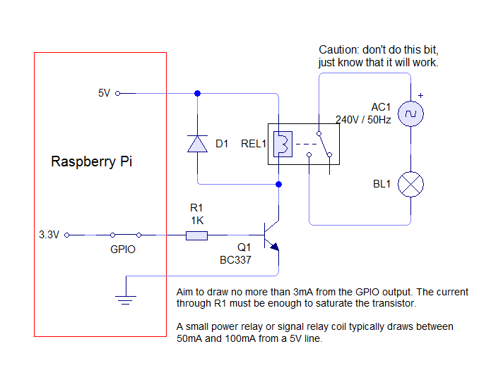
QIANJI JQC-3F(T73)
- http://www.datasheetarchive.com/dlmain/Datasheets-32/DSA-638470.pdf
- looking from above, so the center to left is connected on relay open, and center to right is connected on relay close.
Open Home Automation | Control a relay from anywhere using the Raspberry Pi - Open Home Automation - http://openhomeautomation.net/control-a-relay-from-anywhere-using-the-raspberry-pi/
Easy GPIO Web Interface
Raspberry Pi GPIO - The Easy Way - YouTube - https://www.youtube.com/watch?v=0i2C3Qagosc
Button Audio
- Playing sounds and using buttons with Raspberry Pi | Adafruit Learning System - http://learn.adafruit.com/playing-sounds-and-using-buttons-with-raspberry-pi/
Analog
ADC - Analog to Digital Converter
"The Raspberry Pi computer does not have a way to read analog inputs. It's a digital-only computer" [18]
"We need a way to make the Pi analog-friendly. We'll do that by wiring up an MCP3008 chip to it. The MCP3008 acts like a 'bridge' between digital and analog. It has 8 analog inputs and the Pi can query it using 4 digital pins. That makes it a perfect addition to the Pi for integrating simple sensors like photocells, FSRs or potentiometers, thermistors, etc.!" [19]
References:
- Connecting the Cobbler to a MCP3008 | Analog Inputs for Raspberry Pi Using the MCP3008 | Adafruit Learning System - http://learn.adafruit.com/reading-a-analog-in-and-controlling-audio-volume-with-the-raspberry-pi/connecting-the-cobbler-to-a-mcp3008
- Reading Analogue Sensors With One GPIO Pin | Raspberry Pi Spy - http://www.raspberrypi-spy.co.uk/2012/08/reading-analogue-sensors-with-one-gpio-pin/
- Working with analog sensors in the Raspberry Pi | My rambling weblog of things and…stuff - http://antoniolopes.info/wp/blog/2013/03/05/working-with-analog-sensors-in-the-raspberry-pi/
Drive a Servo Motor
The Raspberry Pi has no analog outputs, so this can be a bit tricky.
Tutorial: Raspberry Pi - How-to Drive a Servo Motor via Arduino! - YouTube - http://www.youtube.com/watch?v=tk0QiiD8w7Q
Sprinkler Control
Group: Raspberry Pi - element14 - http://www.element14.com/community/groups/raspberry-pi
- Carriots | Electrovalve - https://www.carriots.com/tutorials/raspberrypi_carriots/electrovalve
H2O IQ - Raised by Savages - http://blog.valkyriesavage.com/blog/2013/01/18/h2o-iq/
- valkyriesavage-fluffy-toboggans · GitHub - https://github.com/valkyriesavage/fluffy-toboggans
- includes Eagle files
Raspberry Pi – Driving a Relay using GPIO | SusaNET - http://www.susa.net/wordpress/2012/06/raspberry-pi-relay-using-gpio/
Security Alarm Control
- http://www.ebay.com/itm/171075408477
- http://en.wikipedia.org/wiki/Transistor%E2%80%93transistor_logic
- https://www.sparkfun.com/tutorials/215
CPU Temperature
CPU Temp:
# /opt/vc/bin/vcgencmd measure_temp
temp=43.3'C

# cat /sys/class/thermal/thermal_zone0/temp
43312
#!/usr/bin/env python

import subprocess
import re

cmd = "/opt/vc/bin/vcgencmd measure_temp"
p = subprocess.Popen(cmd, shell=True, stdout=subprocess.PIPE, stderr=subprocess.STDOUT)
output = ''.join(p.stdout.readlines())
rc = p.wait()

match = re.findall("temp=([0-9]*\.[0-9]*)'C", output)
if match:
    temp = match[0]

print "{0} C".format(temp)
- Raspberry Pi • View topic - CPU Temperature Recorder - http://www.raspberrypi.org/phpBB3/viewtopic.php?f=31&t=47469
- Raspberry Pi Benchmarks - Roy Longbottom's PC benchmark Collection - http://www.roylongbottom.org.uk/Raspberry%20Pi%20Benchmarks.htm
- Raspberry Pi - ArchWiki - https://wiki.archlinux.org/index.php/Raspberry_Pi
Part of the libraspberrypi-bin package
Waterproof Timelapse Rig
Waterproofing your timelapse rig | Raspberry Pi - http://www.raspberrypi.org/archives/4799
Fotosyn » Simple timelapse camera using Raspberry Pi and a coffee tin - http://www.fotosyn.com/simple-timelapse-camera-using-raspberry-pi-and-a-coffee-tin/
Bitcoin
Bitcoin operated pool table | Raspberry Pi - http://www.raspberrypi.org/archives/4796
-
- Walkthrough: Raspberry Pi/Block Erupter mining rig setup with autostart and vnc - https://bitcointalk.org/index.php?topic=255582.0
- Raspberry Pi • View topic - Bitcoin ASIC Erupter Cgminer - http://www.raspberrypi.org/phpBB3/viewtopic.php?f=63&t=54176
- Mining Bitcoins with USB Block Erupters, a Raspberry Pi and MinePeon | Random Snippets - http://rdmsnippets.com/2013/07/24/mining-bitcoins-with-usb-block-erupters-a-raspberry-pi-and-minepeon/
-
edit /etc/inittab
find the getty's and change one of them eg 6 or add another [but not 7]
e.g. for 3 find
3:23:respawn:/sbin/getty 38400 tty3
and change that to be
3:23:respawn:/usr/local/bin/cgminer

this means when you reboot it will start mining on alt-f3 terminal

you can test this by
sudo kill -HUP 1
to restart init
alt-f3
login file you have a prompt then logout and the miner will start
Serial
Raspberry Pi’s onboard Serial connection | Random Hacks - http://benosteen.wordpress.com/2012/04/24/raspberry-pis-onboard-serial-connection/
FTDI
Serial for security system - some sort of FTDI adapter
Wii Remote
Using Wiimote Wii remote to control Gertboard and Pi via Bluetooth - YouTube - http://www.youtube.com/watch?v=7EAUJGyVNFU
Raspberry Pi + Wii Remote + Python = Awesome!! - YouTube - http://www.youtube.com/watch?v=vEQXFn-KuVs
Nintendo Wii Remote, Python and The Raspberry Pi | Raspberry Pi Spy - http://www.raspberrypi-spy.co.uk/2013/02/nintendo-wii-remote-python-and-the-raspberry-pi/
See #Bluetooth
Install Bluetooth driver:
sudo apt-get install --no-install-recommends bluetooth
Install the CWiid Python Library:
sudo apt-get install python-cwiid
Find Wii remote:
# hcitool scan
Scanning ...
  00:17:AB:26:3F:48       Nintendo RVL-CNT-01
May need to flush:
# hcitool scan --flush --refresh
Get script:
wget http://www.raspberrypi-spy.co.uk/archive/python/wii_remote_1.py
wii_remote_1.py:
#!/usr/bin/python
#+-+-+-+-+-+-+-+-+-+-+-+-+-+-+-+-+-+-+-+-+-+
#|R|a|s|p|b|e|r|r|y|P|i|-|S|p|y|.|c|o|.|u|k|
#+-+-+-+-+-+-+-+-+-+-+-+-+-+-+-+-+-+-+-+-+-+
#
# wii_remote_1.py
# Connect a Nintendo Wii Remote via Bluetooth
# and  read the button states in Python.
#
# Project URL :
# http://www.raspberrypi-spy.co.uk/?p=1101
#
# Author : Matt Hawkins
# Date   : 30/01/2013

# -----------------------
# Import required Python libraries
# -----------------------
import cwiid
import time

button_delay = 0.1

print 'Press 1 + 2 on your Wii Remote now ...'
time.sleep(1)

# Connect to the Wii Remote. If it times out
# then quit.
try:
  wii=cwiid.Wiimote()
except RuntimeError:
  print "Error opening wiimote connection"
  quit()

print 'Wii Remote connected...\n'
print 'Press some buttons!\n'
print 'Press PLUS and MINUS together to disconnect and quit.\n'

wii.rpt_mode = cwiid.RPT_BTN

while True:

  buttons = wii.state['buttons']

  # If Plus and Minus buttons pressed
  # together then rumble and quit.
  if (buttons - cwiid.BTN_PLUS - cwiid.BTN_MINUS == 0):
    print '\nClosing connection ...'
    wii.rumble = 1
    time.sleep(1)
    wii.rumble = 0
    exit(wii)

  # Check if other buttons are pressed by
  # doing a bitwise AND of the buttons number
  # and the predefined constant for that button.
  if (buttons & cwiid.BTN_LEFT):
    print 'Left pressed'
    time.sleep(button_delay)

  if(buttons & cwiid.BTN_RIGHT):
    print 'Right pressed'
    time.sleep(button_delay)

  if (buttons & cwiid.BTN_UP):
    print 'Up pressed'
    time.sleep(button_delay)

  if (buttons & cwiid.BTN_DOWN):
    print 'Down pressed'
    time.sleep(button_delay)

  if (buttons & cwiid.BTN_1):
    print 'Button 1 pressed'
    time.sleep(button_delay)

  if (buttons & cwiid.BTN_2):
    print 'Button 2 pressed'
    time.sleep(button_delay)

  if (buttons & cwiid.BTN_A):
    print 'Button A pressed'
    time.sleep(button_delay)

  if (buttons & cwiid.BTN_B):
    print 'Button B pressed'
    time.sleep(button_delay)

  if (buttons & cwiid.BTN_HOME):
    print 'Home Button pressed'
    time.sleep(button_delay)

  if (buttons & cwiid.BTN_MINUS):
    print 'Minus Button pressed'
    time.sleep(button_delay)

  if (buttons & cwiid.BTN_PLUS):
    print 'Plus Button pressed'
    time.sleep(button_delay)
Another good one: https://sites.google.com/site/brianhensleyfiles/wiimotetest.py
---
HOWTO: Python Wiimote fun (LEDs, rumble, accel, buttons) - maemo.org - Talk - http://talk.maemo.org/showthread.php?t=60178
Count in binary with LEDs:
import cwiid
import time
print "press 1 + 2"
wm = cwiid.Wiimote()
for i in range(16):
    wm.led = i
    print i
    time.sleep(1)
Note: If you want to go fast with LEDs, give a good sleep time after initial connection, or they will all just continue to blink
Rumble:
for i in range(16):
    wm.led = i
    wm.rumble = 1-i%2
    time.sleep(.2)
Last but not least, let's now also get the accelerometer data by enabling the "RPT_ACC" reporting mode (we keep RPT_BTN here as well for the buttons, but don't need to):
wm.rpt_mode = cwiid.RPT_BTN | cwiid.RPT_ACC
wm.state
Let me finish off this short tutorial with a complete example that does the following:
- If the Wiimote is tilted down on the X axis, enable rumble (otherwise disable)
- While the "A" button is pressed, increment the LED counter, otherwise leave it the same
import cwiid
import time

print 'Press 1+2 on your Wiimote now...'
wm = cwiid.Wiimote()

time.sleep(1)

wm.rpt_mode = cwiid.RPT_BTN | cwiid.RPT_ACC

wm.led = 1

while True:
    wm.rumble = (wm.state['acc'][0] < 126)
    if wm.state['buttons'] & cwiid.BTN_A:
        wm.led = (wm.state['led'] + 1) % 16
    time.sleep(.2)
- wm.state['acc'][0] = Roll
- wm.state['acc'][1] = Pitch (bowling)
- wm.state['acc'][2] = Both
Nothing seems to affect Yaw. ("Yaw can only be sensed using the Wiimote Plus addon" [20])
http://embeddedcode.files.wordpress.com/2010/12/pry-wiimote.gif?w=320&h=308
Wiimote and GlovePIE | The Embedded Code - http://embeddedcode.wordpress.com/2010/12/07/wiimote-and-glovepie/
---
PixArt optical sensor?
Follow-up Story: Tearing down the Wii --- 'Sensor Bar' Features No Sensor -- Tech-On! - http://techon.nikkeibp.co.jp/english/NEWS_EN/20061128/124569/
wii.rpt_mode = cwiid.RPT_IR
while True:
    print wii.state
    time.sleep(.2)

# {'led': 0, 'ir_src': [{'pos': (720, 154), 'size': 1}, {'pos': (648, 151), 'size': 1}, None, None],
 'rpt_mode': 8, 'ext_type': 0, 'rumble': 0, 'error': 0, 'battery': 146}
HOWTO: Python Wiimote fun (LEDs, rumble, accel, buttons) - maemo.org - Talk - talk.maemo.org/showthread.php?p=785206#post785206
Solenoid
Ding a bell with a solenoid
Using Wiimote Wii remote to control Gertboard and Pi via Bluetooth - YouTube - http://www.youtube.com/watch?v=7EAUJGyVNFU
Raspberry Pi - IR controlled solenoid alarm bell - YouTube - http://www.youtube.com/watch?v=IkKkYLiNVRE
Pi Cluster
The RPiCluster - YouTube - http://www.youtube.com/watch?v=i_r3z1jYHAc
Beowulf Cluster
Debounce Buffer
RPi Tutorial EGHS:Switch Input - eLinux.org - http://elinux.org/RPi_Tutorial_EGHS:Switch_Input
Opto-isolator
Dream Green House • Features • Raspberry Pi I/O - http://www.dreamgreenhouse.com/features/rpi/io/index.php
"An opto-isolator is basically a light controlled switch. It has the advantages of providing optical isolation and enabling higher voltages to be used to control the input, e.g. 12 V dc shown here. The 2.4 kΩ resistor limits the current into the opto-isolator LED to about 5mA. We typically use a The 3.9 kΩ resistor though, to reduce the current to less than 3 mA. If full electrical isolation is not important, you can also use a common ground. "
"We are using the ILQ74 quad opto-isolator in all of our applications (ILQ74 datasheet). It's cheap and reliable and the input LED is compatible with a wide range of input voltages, including the 3.3V found on the Raspberry Pi. "


-
The Raspberry Pi Hobbyist: GPIO Input Circuit - http://raspberrypihobbyist.blogspot.com/2012/09/gpio-input-circuit_19.html

LDR
RPi Tutorial EGHS:LED output - eLinux.org - http://www.raspberrypi-spy.co.uk/2012/08/reading-analogue-sensors-with-one-gpio-pin/
Analog Sensor
RPi Tutorial EGHS:LED output - eLinux.org - http://www.raspberrypi-spy.co.uk/2012/08/reading-analogue-sensors-with-one-gpio-pin/
GPIO Expansion Board
Slice of PI/O - Ciseco PLC - http://shop.ciseco.co.uk/k002-slice-of-pi-o/
- The Slice of Pi/O gives a Raspberry Pi an extra 16 buffered inputs or outputs. There's now quite a few people making boards with the MCP23017 driver chip on. We think this represents some great lateral thinking and superb design.
Cron
Run script on boot: [21]
@reboot python /home/pi/MyScript.py &
Garage Door
Raspberry Pi Garage Door Opener – With Asterisk Integration - Random Brain Farts By Mr. Harper - http://burkeharper.com/knowledge/?p=112
Seco-larm Alarm Switch Screw Terminals Miniature with 2" Gap - White | SM-217Q/W (SM217QW) | Seco-larm - http://www.mcmelectronics.com/product/82-13869
- The easy-to-install normallyopen magnetic contacts include a wide 2" gap, for use with loose-fitting doors and windows, steel doors, and other applications where wide gaps are found.
---
Raspberry Pi • View topic - Sensing when Garage Door is Open - http://www.raspberrypi.org/phpBB3/viewtopic.php?f=37&t=9770
Raspberry Pi • View topic - Opening Garage Door with Pi - http://www.raspberrypi.org/phpBB3/viewtopic.php?f=37&t=10030&p=113972
Powered USB Hub
RPi Powered USB Hubs - eLinux.org - http://elinux.org/RPi_Powered_USB_Hubs
Amazon.com : 10 Port USB 2.0 Hub : Usb Network Adapters : Electronics ($9 w/ Prime) - http://amzn.com/B00475WJEY
- AC/DC Adapter (2A @ 5.0V)

NFS
Error:
# mount prime:/pub mnt
mount.nfs: rpc.statd is not running but is required for remote locking.
mount.nfs: Either use '-o nolock' to keep locks local, or start statd.
mount.nfs: an incorrect mount option was specified
update-rc.d rpcbind defaults
service rpcbind restart
mount prime:/pub /pub
--- Server ---
apt-get install nfs-kernel-server   # alias: nfs-server
service nfs-kernel-server restart
update-rc.d nfs-kernel-server defaults
/etc/exports
/pub            10.10.10.0/24(rw,no_root_squash,no_all_squash,sync)
/hdd            10.10.10.0/24(rw,no_root_squash,no_all_squash,sync)
If it doesn't start in the appropriate runlevel: [22]
for i in 0 1 6; do ln -s ../init.d/rpcbind /etc/rc$i.d/K07rpcbind; done
for i in 2 3 4 5 S; do ln -s ../init.d/rpcbind /etc/rc$i.d/S12rpcbind; done
update-rc.d rpcbind defaults
ASIC Bit Coin Mining
See Bitcoin#Mining
---
Recommended to use an older version on Raspberry Pi:
Initial Setup & Overview | PiMiner Raspberry Pi Bitcoin Miner | Adafruit Learning System - http://learn.adafruit.com/piminer-raspberry-pi-bitcoin-miner/initial-setup-and-assembly
Install Software | PiMiner Raspberry Pi Bitcoin Miner | Adafruit Learning System - http://learn.adafruit.com/piminer-raspberry-pi-bitcoin-miner/install-cgminer
sudo apt-get update
sudo apt-get install libusb-1.0-0-dev libusb-1.0-0 libcurl4-openssl-dev libncurses5-dev libudev-dev

wget http://ck.kolivas.org/apps/cgminer/3.1/cgminer-3.1.1.tar.bz2
tar xvf cgminer-3.1.1.tar.bz2
cd cgminer-3.1.1
./configure --enable-icarus
make

cat > cgminer.conf << EOF
{
    "api-allow": "0/0",
    "api-listen": true,
    "api-port": "4028",
    "expiry": "120",
    "failover-only": true,
    "icarus-options": "115200:1:1",
    "icarus-timing": "3.0=100",
    "kernel-path": "/usr/local/bin",
    "log": "5",
    "no-pool-disable": true,
    "pools": [
        {
            "pass": "[PASSWORD]",
            "url": "http://pit.deepbit.net:8332",
            "user": "[USERNAME]"
        }
    ],
    "queue": "2",
    "scan-time": "60",
    "shares": "0",
    "worktime": true
}
EOF

ls /dev/*USB*

# sudo nohup ./cgminer-3.1.1/cgminer --config /home/pi/cgminer.conf -S /dev/ttyUSB0 -S /dev/ttyUSB1 >/dev/null 2>&1&
sudo nohup ./cgminer --config cgminer.conf -S /dev/ttyUSB0 >/dev/null 2>&1&
---
PiMiner
git clone https://github.com/adafruit/PiMiner.git
Forked to: https://github.com/kiloforce/cgminerminer
git clone https://github.com/kiloforce/cgminerminer.git
Apache
apt-get install apache2 php5
VNC Server
# alias: sudo apt-get install vnc-server
sudo apt-get install tightvncserver
tightvncserver  # set password
vncserver :0 -geometry 1920x1080 -depth 24
vim svnc.sh
#!/bin/sh
vncserver :0 -geometry 1920x1080 -depth 24 -dpi 96
/usr/bin/vncserver :0 -geometry 1280x800 -depth 16 -pixelformat rgb565
vncserver :0 -geometry 1024x768 -depth 16 &
References:
- RPi VNC Server - eLinux.org - http://elinux.org/RPi_VNC_Server
- Setting up Remote Desktop for Your CentOS or Fedora Linux Dedicated Server | Go Daddy Help | GoDaddy Support - http://support.godaddy.com/help/article/6012/setting-up-remote-desktop-for-your-centos-or-fedora-linux-dedicated-server#access
---
/root/.vnc/xstartup
#!/bin/sh

xrdb $HOME/.Xresources
xsetroot -solid grey
#x-terminal-emulator -geometry 80x24+10+10 -ls -title "$VNCDESKTOP Desktop" &
#x-window-manager &
# Fix to make GNOME work
export XKL_XMODMAP_DISABLE=1
/etc/X11/Xsession
Which looks like it runs LXDE
LXDE - Lightweight X11 Desktop Environment
VNC Desktop
To share the current desktop:
sudo apt-get install x11vnc
# as user 'pi'
x11vnc -display :0
Or if you want vnc server run after login, you can automate with this script:
#!/bin/bash
/usr/bin/x11vnc -nap -wait 50 -noxdamage -passwd PASSWORD -display :0 -forever -o /var/log/x11vnc.log -bg
get that running on GDM in case the machine isn't already logged in:
x11vnc -display :0 -auth /var/lib/gdm/:0.Xauth
From an SSH session, to start an app on the desktop:
export DISPLAY=:0
xterm
References:
- fedora - Enable remote desktop for Gnome from command line? - Unix & Linux Stack Exchange - http://unix.stackexchange.com/questions/73041/enable-remote-desktop-for-gnome-from-command-line
Firmware
rpi-update - An easier way to update the firmware of your Raspberry Pi.
Hexxeh/rpi-update - GitHub - https://github.com/Hexxeh/rpi-update
To update your firmware (and kernel), just run the following command:
sudo rpi-update
To upgrade/downgrade to a specific firmware revision, specify its Git hash (from the https://github.com/Hexxeh/rpi-firmware now https://github.com/raspberrypi/rpi-firmware repository) as follows:
sudo rpi-update b62ec22eac11772e3a013a0faedd6d790da23c66
---
Check your firmware version
Using the latest firmware version may help various problems with SD card and display compatibility. Check the kernel version with:
# uname -a
Linux pi-sprinkler 3.6.11+ #538 PREEMPT Fri Aug 30 20:42:08 BST 2013 armv6l GNU/Linux
And the GPU firmware with:
# /opt/vc/bin/vcgencmd version
Sep  1 2013 23:25:25
Copyright (c) 2012 Broadcom
version 4f9d19896166f46a3255801bc1834561bf092732 (clean) (release)
Note, the version that is displayed here will not match the hash downloaded by rpi-update. Not sure why.
---
"The software package called "raspberrypi-bootloader" also contains the firmware. This will be updated by apt-get upgrade.
The rpi-update command will load the latest "cutting edge" version of the firmware. Occasionally this can cause minor problems, and very rarely could cause your Pi to fail to start up. Unless you need the latest version you are probably better off with apt-get upgrade." [23]
--- References:
- operating systems - Do I still need rpi-update if I am using the latest version of Raspbian? - Raspberry Pi Stack Exchange - http://raspberrypi.stackexchange.com/questions/4355/do-i-still-need-rpi-update-if-i-am-using-the-latest-version-of-raspbian
- R-Pi Troubleshooting - eLinux.org - Updating firmware - http://elinux.org/R-Pi_Troubleshooting#Updating_firmware
- Raspberry Pi • View topic - Pi Firmware - http://www.raspberrypi.org/phpBB3/viewtopic.php?f=29&t=40553
MPEG-2 DVD License
Raspberry Pi • View topic - Playing DVD movies on the R Pi - http://www.raspberrypi.org/phpBB3/viewtopic.php?f=38&t=45502
How To Add MPEG 2 To Your Raspberry Pi Media Centre - http://www.makeuseof.com/tag/how-to-add-mpeg-2-to-your-raspberry-pi-media-centre/
Raspberry Pi Store - http://www.raspberrypi.com/
about $4 for MPEG-2 license key
MPG2 Decode keys go in /boot/config.txt
decode_MPG2=0x12345678,0xabcdabcd,0x87654321
Testing Codecs to see if they are Enabled [24]
/opt/vc/bin/vcgencmd codec_enabled MPG2
MPG2=disabled
MAME
References:
- Raspberry Pi • View topic - RetroPie in RaspBMC - http://www.raspberrypi.org/phpBB3/viewtopic.php?f=78&t=37693
- petrockblog/RetroPie-Setup · GitHub - https://github.com/petrockblog/RetroPie-Setup
- MAME Arcade Game Fun With A Raspberry Pi | The Developer's Tidbits - http://devtidbits.com/2012/11/26/mame-arcade-game-fun-with-a-raspberry-pi/
- Raspbian on Raspberry Pi – MAME, MESS, Quake3, NeoGeo, and Cave Story Binaries | Shea Silverman's Blog - http://blog.sheasilverman.com/2012/07/raspbian-on-raspberry-pi-mame-mess-quake3-neogeo-and-cave-story-binaries/
- mame4all-pi - MAME4all for the Raspberry Pi - Google Project Hosting - http://code.google.com/p/mame4all-pi/
- MAME | Raspberry Pi - http://www.raspberrypi.org/archives/tag/mame
- Turn an old CRT Television into a Raspberry Pi Powered MAME Cocktail Cabinet : Getting MAME working - http://www.instructables.com/id/Turn-an-old-CRT-Television-into-a-Raspberry-Pi-Pow/step2/
- A Straightforward Guide to Arcade Emulation on the Raspberry Pi - Tested - http://www.tested.com/tech/gaming/456272-straightforward-guide-arcade-emulation-raspberry-pi/
- Overview | Retro Gaming with Raspberry Pi | Adafruit Learning System - http://learn.adafruit.com/retro-gaming-with-raspberry-pi
- adafruit/Adafruit-Retrogame · GitHub - https://github.com/adafruit/Adafruit-Retrogame
- Massive Arcade Button with LED - 100mm Red ID: 1185 - $9.95 : Adafruit Industries, Unique & fun DIY electronics and kits - http://www.adafruit.com/products/1185
- PiMAME | Gaming and Emulators for the Raspbery Pi | Shea Silverman - http://pimame.org/
- Tutorials - PiMAME | Gaming and Emulators for the Raspbery Pi | Shea Silverman - http://pimame.org/quickstart.html
uinput - Uinput is Linux kernel module which allows attaching userspace device drivers into the Linux kernel. However, its ioctl-interface is pretty low level from an application developer's perspective. This library provides a set of helper functions for making the usage of uinput easier. Libsuinput can be considered thin, because it operates on the same file descriptors as traditional ioctl commands.
- c - Ensuring that uinput (kernel module) is indeed running/loaded plus some test code - Stack Overflow - http://stackoverflow.com/questions/11899557/ensuring-that-uinput-kernel-module-is-indeed-running-loaded-plus-some-test-cod
- Getting started with uinput: the user level input subsystem - http://thiemonge.org/getting-started-with-uinput
- tuomasjjrasanen/libsuinput · GitHub - https://github.com/tuomasjjrasanen/libsuinput
- Adding Arcade Controls | Retro Gaming with Raspberry Pi | Adafruit Learning System - http://learn.adafruit.com/retro-gaming-with-raspberry-pi/buttons
Video
omxplayer
omxplayer /pub/Gethsemane_Song_Stories_of_Jesus.mp4
omxplayer -o hdmi /path/to/filename.mp4
can play are H264 or Xvid
Full screen: [25]
omxplayer -r VIDEOFILE
xterm -fullscreen -fg black -bg black -e omxplayer -o hdmi -r VIDEOFILE
Then right click one of your avi files and select open with, then click custom command line tool, type in: [26] xterm -fullscreen -fg black -bg black -e omxplayer -o hdmi -r %f
Omxplayer Key Bindings: [27] [28] [29] [30]
Space or p   Pause/Resume
q            Exit OMXPlayer
z            Show Info (doesn't appear to work)

-            Decrease Volume
+            Increase Volume

i            Previous Chapter
o            Next Chapter

Left Arrow   Seek -30
Right Arrow  Seek +30
Down Arrow   Seek -600
Up Arrow     Seek +600

1            Increase Speed
2            Decrease Speed

j            Previous Audio stream
k            Next Audio stream

n            Previous Subtitle stream
m            Next Subtitle stream
s            Toggle subtitles
d            Subtitle delay -250 ms
f            Subtitle delay +250 ms
handbrake-cli [31]
handbrake-cli -i outDir -o movie.mp4 -e x264 -q 20 -B 160 -t 1
  -q quality
  -B audio compress rate in Kbps
  -t title id to convert
  -e encode format
References:
- Raspberry Pi • View topic - How to play video on a Pi ? - http://www.raspberrypi.org/phpBB3/viewtopic.php?f=26&t=10419
- Omxplayer - eLinux.org - http://elinux.org/Omxplayer
you tube
youtube-dl - downloader of videos from YouTube and other sites
apt-get install youtube-dl
Updated self:
youtube-dl -U
Download a video:
youtube-dl http://www.youtube.com/watch?v=vKtwZmhX0lw
Download multiple videos:
youtube-dl -a youtube_links.txt
---
Download video:
youtube-dl http://www.youtube.com/watch?v=6E2hYDIFDIU
Get video title:
youtube-dl --get-title http://www.youtube.com/watch?v=6E2hYDIFDIU
Extract audio:
ffmpeg -i 6E2hYDIFDIU.flv 6E2hYDIFDIU.wav
Convert to mp3:
lame 6E2hYDIFDIU.wav 6E2hYDIFDIU.mp3
youtube2mp3.sh:
#!/bin/bash
    # A very simple Bash script to download a YouTube video
    # and extract the music file from it.
address=$1
regex='v=(.*)'
if [[ $address =~ $regex ]]; then
  video_id=${BASH_REMATCH[1]}
  video_id=$(echo $video_id | cut -d'&' -f1)
  video_title="$(youtube-dl --get-title $address)"
  youtube-dl $address
  ext="flv"
  ffmpeg -i $video_id.$ext "$video_title".wav
  lame "$video_title".wav "$video_title".mp3
  rm $video_id.$ext "$video_title".wav
else
  echo "Sorry but the system encountered a problem."
fi
-
Play file directly:
youtube-dl -g "http://www.youtube.com/video?v=xyzpdq" | xargs omxplayer -o hdmi
References:
- Grabbing Your Music from YouTube: Do It Your Way | Linux Journal - http://www.linuxjournal.com/content/grabbing-your-music-youtube-do-it-your-way
---
GPS
Android: Llama, Tasked Tasker, Locale
--
GPS - BlueNEXT GPS USB dongle
Dream Green House • Features • Raspberry Pi - http://dreamgreenhouse.com/features/rpi/gps/index.php

Referenced:
- Raspberry Pi Dashcam Project - http://dreamgreenhouse.com/projects/2013/picar/
- "We have now successfully added a USB GPS module. The Raspberry Pi does not have a clock by default and we are using the GPS dongle to provide an accurate clock. We also have other plans to use the GPS module for speed and location logging. This part is described in our RPi GPS feature. "
COSM / Xively
COSM used to be Pachube, and is now Xively (by LogMeIn).
Overview | Send Raspberry Pi Data to COSM | Adafruit Learning System - http://learn.adafruit.com/send-raspberry-pi-data-to-cosm/overview
- "The combination of connecting a Raspberry Pi to COSM makes creating a internet of things much easier than it has been in the past. The Pi with it's easy access to ethernet / WiFi and COSM's drop dead simple usability will graph all sensor data you send to it. This tutorial explains how to connect a analog temperature sensor to the Pi and use a small python script to upload that data for storage and graphing on COSM."
Power Monitoring with hacked Kill-A-Watt
RaspiWatt: discover power consumption using a Kill-A-Watt & Pi - www.raspihub.com/go/393f732cc14546ee0e904c1d434b3568db23dec5eca542961ca32d6317a2a798
rsync
Throttle rsync with: [32]
ionice /usr/bin/rsync --progress [SRC] [DEST]
Serial to USB Converter
TRENDnet TU-S9
[319746.693652] usb 1-1.3.4: new full-speed USB device number 34 using dwc_otg
[319746.819230] usb 1-1.3.4: New USB device found, idVendor=067b, idProduct=2303
[319746.819268] usb 1-1.3.4: New USB device strings: Mfr=1, Product=2, SerialNumber=0
[319746.819287] usb 1-1.3.4: Product: USB-Serial Controller D
[319746.819306] usb 1-1.3.4: Manufacturer: Prolific Technology Inc.
[319746.900332] usbcore: registered new interface driver usbserial
[319746.902466] usbcore: registered new interface driver usbserial_generic
[319746.902639] usbserial: USB Serial support registered for generic
[319746.914086] usbcore: registered new interface driver pl2303
[319746.914803] usbserial: USB Serial support registered for pl2303
[319746.914975] pl2303 1-1.3.4:1.0: pl2303 converter detected
[319746.928766] usb 1-1.3.4: pl2303 converter now attached to ttyUSB0
/dev/ttyUSB0
X10
"The two dominant standards for powerline transmission are Insteon and X10" [33]
References:
- X10 Smart House Home Automation Using Debian Linux - http://www.aboutdebian.com/x10.htm
- Build your own wake-up light alarm using X10, Raspberry Pi & Linux | harmdelaat.com - http://harmdelaat.com/build-your-own-wake-up-light-alarm-using-x10-rapsberry-pi-linux/
- Home Automation Hardware (X10, Server, etc.) | Do-It-Yourself Home Automation - http://diy-ha.com/home-automation-hardware-x10-server-etc/
- X10 (industry standard) - Wikipedia, the free encyclopedia - http://en.wikipedia.org/wiki/X10_%28industry_standard%29
heyu
See heyu
mochad
mochad is a Linux TCP gateway daemon for the X10 CM15A RF (radio frequency) and PL (power line) controller and the CM19A RF controller.
echo "pl a1 on" | nc localhost 1099
echo "pl a1 off" | nc locahost 1099
References:
- Installing mochad on a Raspberry Pi | X10 Linux - http://x10linux.blogspot.com/2012/08/installing-mochad-on-raspberry-pi.html
Arduino
Arduino IDE
Menu -> Electronics -> Arduino IDE
- runs the command '/usr/bin/arduino'
3 Packages:
arduino - AVR development board IDE and built-in libraries
arduino-core - Code, examples, and libraries for the Arduino platform
arduino-mk - Program your Arduino from the command line
Installation:
apt-get install arduino
If you want to be able to run from the command line:
apt-get install arduino-mk
# or
pip install ino
Getting Started
Open the blink example
Open the LED blink example sketch: File > Examples > 1.Basics > Blink.
A few seconds after the upload finishes, you should see the pin 13 (L) LED on the board start to blink (in orange). If it does, congratulations! You've gotten Arduino up-and-running.
Arduino Getting Started - Windows - http://arduino.cc/en/Guide/Windows
Arduino UNO
# dmesg
[204411.055236] usb 1-1.3.6: new full-speed USB device number 8 using dwc_otg
[204411.191446] usb 1-1.3.6: New USB device found, idVendor=2341, idProduct=0043
[204411.191479] usb 1-1.3.6: New USB device strings: Mfr=1, Product=2, SerialNumber=220
[204411.191496] usb 1-1.3.6: Manufacturer: Arduino (www.arduino.cc)
[204411.191511] usb 1-1.3.6: SerialNumber: 9523732383435151C091
[204411.261127] cdc_acm 1-1.3.6:1.0: ttyACM0: USB ACM device
[204411.267605] usbcore: registered new interface driver cdc_acm
[204411.267635] cdc_acm: USB Abstract Control Model driver for USB modems and ISDN adapters
/dev/ttyACM0
Raspberry Pi vs Arduino
Raspberry Pi and Arduino | Raspberry Pi - http://www.raspberrypi.org/archives/1171
- "Ultimately, we hope that successful sales of Raspberry Pi will encourage people to buy Arduinos too, and vice versa: the two have what I believe business school-types call “good synergy”."
Raspberry Pi to Arduino Serial Communication
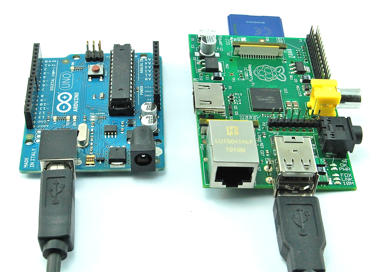
Arduino Blink Test - When it receives a digit, it flashes the number of times indicated by the digit.
const int ledPin = 13;

void setup()
{
  pinMode(ledPin, OUTPUT);
  Serial.begin(9600);
}

void loop()
{
  Serial.println("Hello Pi");
  if (Serial.available())
  {
     flash(Serial.read() - '0');
  }
  delay(1000);
}

void flash(int n)
{
  for (int i = 0; i < n; i++)
  {
    digitalWrite(ledPin, HIGH);
    delay(100);
    digitalWrite(ledPin, LOW);
    delay(100);
  }
}
There is a Python library for serial communications called 'pySerial' which has history with Arduino.
import serial
ser = serial.Serial('/dev/ttyACM0', 9600)

while 1 :
    ser.readline()

# force a break then test sending...

ser.write('5')
A simple UI with Python and GTK [34]
References:
- Dr. Monk's DIY Electronics Blog: Raspberry Pi and Arduino - http://www.doctormonk.com/2012/04/raspberry-pi-and-arduino.html
- Dr. Monk's DIY Electronics Blog: Raspberry Pi meets Arduino - part 2 - http://www.doctormonk.com/2012/07/raspberry-pi-meets-arduino-part-2.html
- Arduino Playground - Python - http://playground.arduino.cc/Interfacing/Python
Pandora Internet Radio
Instructables - Arduino / Raspberry Pi Internet Radio - http://www.instructables.com/id/Arduino-Raspberry-Pi-Internet-Radio/
- Raspberry Pi runs mpd music player daemon to receive and decode the internet radio stream.
- ALSA running on the Raspberry Pi provides the sound through either the Jack Socket or the HDMI output.
- We want to control the Radio from the Buttons on the Arduino and we want to see which Radio Station we're listening to on the LCD display.
--
Note: Pidora - is not what we are looking for!
pianobar
pianobar - console based player for Pandora radio
Install and Configure:
apt-get install pianobar

mkdir -p ~/.config/pianobar

cat > ~/.config/pianobar/config << "EOF"
user = [USERNAME]
password = [PASSWORD]
tls_fingerprint = 2D0AFDAFA16F4B5C0A43F3CB1D4752F9535507C0
autostart_station = 713040038180498234
EOF

# make sure audio is going to audio jack
amixer cset numid=3 1

pianobar
---
Control Piano Bar
mkfifo ~/.config/pianobar/ctl
New song:
echo -n 'n' > ~/.config/pianobar/ctl
Another example:
while true; do;
    nc -l -p 12345 -s localhost localhost > ~/.config/pianobar/ctl;
    sleep 1;
done

echo -ne 'n\x1a' | nc -q 0 127.0.0.1 12345
---
Autostart a station: [36]
autostart_station = 713040038180498234
When you run pianobar, and you select a station it says
|> Station "{station name}" ({station number})
I believe you just copy {station number} and replace 123456 in the example with that.
---
Error about fingerprint:
Get fingerprint: [37]
openssl s_client -connect tuner.pandora.com:443 < /dev/null 2> /dev/null | \
openssl x509 -noout -fingerprint | tr -d ':' | cut -d'=' -f2
Another:
fingerprint=`openssl s_client -connect tuner.pandora.com:443 < /dev/null 2> /dev/null | openssl x509 -noout -fingerprint | tr -d ':' | \
cut -d'=' -f2` && echo tls_fingerprint = $fingerprint >> ~/.config/pianobar/config
---
Finally, enter the following command to make sure audio is routed to the headphone jack rather than the HDMI port (you can skip this step if using a USB audio device):
sudo amixer cset numid=3 1
---
Configuration examples:
---
Wireless Raspberry Pi Radio: Pianobar - Instructables - http://www.instructables.com/id/Wireless-Raspberry-Pi-Radio-Pianobar/
Pandora's Box - An Internet Radio player made with a Raspberry Pi! - Instructables - http://www.instructables.com/id/Pandoras-Box-An-Internet-Radio-player-made-with/
Turning your raspberry pi into a remote Pandora music box, part 1 | Claire Vo Lawless - http://clairevo.com/post/47546482645/turning-your-raspberry-pi-into-a-remote-pandora-music
Issues
handle_hc_chhltd_intr_dma - DMA Mode - ChHltd set, but reason for halting is unknown
[  247.414548] ERROR::handle_hc_chhltd_intr_dma:2592: handle_hc_chhltd_intr_dma: Channel 7,
DMA Mode -- ChHltd set, but reason for halting is unknown, hcint 0x00000012, intsts 0x04400001
[  345.628872] ERROR::handle_hc_chhltd_intr_dma:2592: handle_hc_chhltd_intr_dma: Channel 1,
DMA Mode -- ChHltd set, but reason for halting is unknown, hcint 0x00000012, intsts 0x04400001
[ 5688.587194] ERROR::handle_hc_chhltd_intr_dma:2592: handle_hc_chhltd_intr_dma: Channel 5,
DMA Mode -- ChHltd set, but reason for halting is unknown, hcint 0x00000012, intsts 0x04600001
[ 5764.631908] cp210x ttyUSB3: cp210x_open - Unable to enable UART
[ 5767.213534] cp210x ttyUSB3: cp210x_open - Unable to enable UART
[ 5768.516800] cp210x ttyUSB3: cp210x_open - Unable to enable UART
[ 5771.479220] cp210x ttyUSB2: cp210x_open - Unable to enable UART
[ 5773.653528] cp210x ttyUSB2: cp210x_open - Unable to enable UART
- Raspberry Pi • View topic - ERROR::handle_hc_chhltd_intr_dma:2537: - http://www.raspberrypi.org/phpBB3/viewtopic.php?t=49840
- Raspberry Pi • View topic - [SOLVED] Wireless no longer working - latest kernel? - http://www.raspberrypi.org/phpBB3/viewtopic.php?t=49223
- Raspberry Pi • View topic - Wired network disconnect when samba transfer is initiated - http://www.raspberrypi.org/phpBB3/viewtopic.php?t=49902
This channel is already in use, continuing anyway
python gpio_test_script.py
RuntimeWarning: This channel is already in use, continuing anyway. Use GPIO.setwarnings(False) to disable warnings.
The pins are configured in a bad state at boot. The first time you run any of script using a GPIO pin you will get this error.
At the begging:
#Alerts OFF
GPIO.setwarnings(False)
At the end:
try:
     main
finally:
     GPIO.cleanup()
"It's all to do with Linux "exporting" the gpio to be visible to a user, so an ordinary user can read and write the gpio. The external program should have "unexported" the gpio when it was finished." [38]
Models
View of Model A
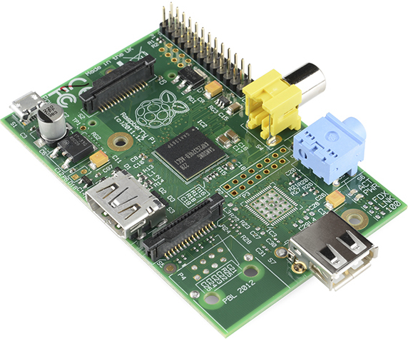
View of Model B
http://upload.wikimedia.org/wikipedia/commons/3/3d/RaspberryPi.jpg?breakwiki=.xxx
Remote Desktop Sharing
sudo apt-get install dconf-editor
dconf-editor # as pi user, org -> gnome -> desktop -> remote access -> [ ] encryption
sudo apt-get install vino
vino-preferences
RPi VNC Screen Sharing - eLinux.org - http://elinux.org/RPi_VNC_Screen_Sharing
---
sudo apt-get install vino dconf-editor

# as pi user...
gsettings set org.gnome.Vino require-encryption false
gsettings set org.gnome.Vino prompt-enabled false
gsettings set org.gnome.Vino authentication-methods "['none']"


## sudo su -
## cat > /etc/sudoers.d/vsrv.sh << "EOF"
## #!/bin/bash
## /usr/lib/vino/vino-server
## EOF
## chmod +x /etc/sudoers.d/vsrv.sh
##
## cat >> /etc/xdg/lxsession/LXDE/autostart << "EOF"
## @/etc/sudoers.d/vsrv.sh
## EOF

sudo su -
cat > /etc/xdg/autostart/vino-server.desktop << "EOF"
[Desktop Entry]
Name=Desktop Sharing
Comment=GNOME Desktop Sharing Server
Exec=/usr/lib/vino/vino-server
Terminal=false
Type=Application
X-GNOME-Autostart-Phase=Applications
X-GNOME-AutoRestart=true
NoDisplay=true
EOF
RPi VNC Screen Sharing - eLinux.org - http://elinux.org/RPi_VNC_Screen_Sharing
Disable pi password warning
SSH is enabled and the default password for the 'pi' user has not been changed.
This is a security risk - please login as the 'pi' user and type 'passwd' to set a new password.
Solution: [39]
- remove /etc/profile.d/sshpasswd.sh (now /etc/profile.d/sshpwd.sh)
Disable wifi warning
- remove /etc/profile.d/wifi-country.sh
Upgrade Bullseye to Bookworm
apt-get update
apt-get upgrade
apt-get dist-upgrade
apt-get full-upgrade
reboot
dpkg -C
apt-mark showhold
dpkg --audit
dpkg --get-selections | grep hold
sudo rpi-update
sed -i 's/bullseye/bookworm/g' /etc/apt/sources.list
# look for any missed references
grep -lnr bullseye /etc/apt
cd /etc/apt/sources.list.d/
for i in *.list ; do sed -i 's/bullseye/bookworm/g' $i ; done
apt-get update
apt-get --simulate upgrade
apt-get upgrade
apt-get dist-upgrade
apt-get autoremove
apt-get autoclean
rpi-update
cat /etc/os-release
reboot
References:
- Raspbian GNU/Linux upgrade from Jessie to Raspbian Stretch 9 - LinuxConfig.org - https://linuxconfig.org/raspbian-gnu-linux-upgrade-from-jessie-to-raspbian-stretch-9
- How to Upgrade Debian 8 (Jessie) to 9 (Stretch) safely - https://www.howtoforge.com/tutorial/how-to-upgrade-debian-8-jessie-to-9-stretch/
- Upgrade Raspbian Jessie to Stretch - bad.robot - http://baddotrobot.com/blog/2017/10/26/upgrade-raspian-jessie-to-stretch/
Upgrade Jessie to Stretch
apt-get update
apt-get upgrade
apt-get dist-upgrade
apt-get full-upgrade
# reboot
dpkg -C
apt-mark showhold
dpkg --audit
dpkg --get-selections | grep hold
sudo rpi-update
sed -i 's/jessie/stretch/g' /etc/apt/sources.list
grep -lnr jessie /etc/apt
apt-get update
apt-get --simulate upgrade
apt-get upgrade
apt-get dist-upgrade
apt-get autoremove
apt-get autoclean
rpi-update
cat /etc/os-release
reboot
References:
- Raspbian GNU/Linux upgrade from Jessie to Raspbian Stretch 9 - LinuxConfig.org - https://linuxconfig.org/raspbian-gnu-linux-upgrade-from-jessie-to-raspbian-stretch-9
- How to Upgrade Debian 8 (Jessie) to 9 (Stretch) safely - https://www.howtoforge.com/tutorial/how-to-upgrade-debian-8-jessie-to-9-stretch/
- Upgrade Raspbian Jessie to Stretch - bad.robot - http://baddotrobot.com/blog/2017/10/26/upgrade-raspian-jessie-to-stretch/
tmpfs
Extending the life of your Raspberry PI SD Card - Domotic Project
https://domoticproject.com/extending-life-raspberry-pi-sd-card/
4.1 /run and /run/lock
4.2 /dev/shm
4.3 /var and /var/tmp
4.4 /var/log
4.5 /var/www/html
4.6 /var/lib/weewx
4.7 /var/lib/upsd
tmpfs
Extending the life of your Raspberry PI SD Card - Domotic Project
https://domoticproject.com/extending-life-raspberry-pi-sd-card/
4.1 /run and /run/lock
4.2 /dev/shm
4.3 /var and /var/tmp
4.4 /var/log
4.5 /var/www/html
4.6 /var/lib/weewx
4.7 /var/lib/upsd
Under Voltage Warning
hwmon hwmon1: Voltage normalised
hwmon hwmon1: Undervoltage detected!
If the Red Power LED is not illuminated this means the supply voltage is inadequate. (The newer Pi have a well engineered power circuit, and may continue to function even if the input voltage is below spec; the same may not be true of peripherals). The GUI had an rainbow indicator (replaced by a lightning bolt) which comes up in the top right if the voltage is inadequate. This has a 3 second timer, and may display even if the LED appears to be lit.
NOTE the Red Power LED on the Pi3B+ only functions if the SD Card/USB key has up to date firmware because it is controlled by software - it is meaningless otherwise.
-
Check throttled, due to under voltage:
vcgencmd get_throttled
$ vcgencmd get_throttled
throttled=0x50000

$ vcgencmd get_throttled
throttled=0x50005

1110000000000000010
|||             |||_ under-voltage
|||             ||_ currently throttled
|||             |_ arm frequency capped
|||_ under-voltage has occurred since last reboot
||_ throttling has occurred since last reboot
|_ arm frequency capped has occurred since last reboot
-
| Bit | Meaning |
|:---:|---------|
| 0 | Under-voltage detected |
| 1 | Arm frequency capped |
| 2 | Currently throttled |
| 3 | Soft temperature limit active |
| 16 | Under-voltage has occurred |
| 17 | Arm frequency capped has occurred |
| 18 | Throttling has occurred |
| 19 | Soft temperature limit has occurred
The bits represent:
throttled=0x50000
0101 0000 0000 0000 0000
throttled=0x50005
0101 0000 0000 0000 0101
bits 0 & 16 - Under-voltage detected (has occured)
bits 2 & 18 - Currently throttled (has occured)
-
root@mypi:~# vcgencmd get_throttled
throttled=0x50005
The 5 on the left means it has been throttled before (since boot), and the 5 on the right means it is currently throttled.
-
root@mypi:~#  vcgencmd get_throttled
throttled=0x50000
The 5 on the left means it has been throttled before (since boot), and the 0 on the right means it is currently not throttled.
-
root@mypi:~# vcgencmd get_throttled
throttled=0x0
This means it has never throttled (since boot).
-
$ vcgencmd get_throttled
throttled=0x50005
The bits represent:
0101 0000 0000 0000 0101

0: under-voltage
1: arm frequency capped
2: currently throttled

16: under-voltage has occurred
17: arm frequency capped has occurred
18: throttling has occurred
under-voltage occurs when voltage drops below 4.63V. The Pi is throttled arm frequency capped occurs with temp > 80'C over-temperature occurs with temp > 85'C. The Pi is throttled
Throttling removes turbo mode, which reduces core voltage, and sets arm and gpu frequencies to non-turbo value. Capping just limits the arm frequency (somewhere between 600MHz and 1200MHz) to try to avoid throttling. If you are throttled and not under-voltage then you can assume over-temperature. (confirm with vcgencmd measure_temp).
So 0x50005 means you are currently under-voltage and throttled
Ref: [40]
-
You can not monitor voltage, because the Pi has no analog capability. (You could, of course, add an ADC to monitor the voltage.)
The under-voltage warning is produced by a chip, and is ON or OFF. See Raspberry Pi Power Limitations (http://raspberrypi.stackexchange.com/questions/51615/raspberry-pi-power-limitations) for details.
vcgencmd get_throttled will show the current state. You may be able to write something to monitor this, but AFAIK there is nothing currently available. See the following for detail https://www.raspberrypi.org/forums/viewtopic.php?f=63&t=147781&start=50#p972790
https://raspberrypi.stackexchange.com/a/72473
-
Troubleshooting power problems - https://elinux.org/R-Pi_Troubleshooting#Troubleshooting_power_problems
Test between TP1 and TP2 (test points). You should see a voltage between 4.75 and 5.25 volts

Ignore Under Voltage Warnings
https://github.com/raspberrypi/documentation/pull/3064/files
"If the power supply to the Raspberry Pi drops below 4.63V (±5%), the following icon is displayed."
https://www.raspberrypi.com/documentation/computers/legacy_config_txt.html#avoid_warnings
avoid_warnings=2 allows turbo mode even when low-voltage is present.
If you want to live ignorantly, you can disable the on-screen warnings: [1]
/boot/config.txt
  avoid_warnings=1
# still get throttled, but no more on-screen warnings (still displays to console)
$ vcgencmd get_throttled
throttled=0x50005
If you want to live dangerously, you can disable the warnings, and disable throttling:
/boot/config.txt
  avoid_warnings=2
# throttled will give something differently
$ vcgencmd get_throttled
throttled=0x70000
Turbo Mode
force_turbo=1
disable_auto_turbo=1
On Raspberry Pi 2 and 3, setting this flag will disable the GPU from moving into turbo mode, which it can do under particular loads.
Setting any overclocking parameters to values other than those used by raspi-config may set a permanent bit within the SoC. This makes it possible to detect that your Raspberry Pi was once overclocked. The overclock bit sets when force_turbo is set to 1 and any of the over_voltage_* options are set to a value of more than 0. See the blog post on Turbo mode for more information. - https://www.raspberrypi.com/news/introducing-turbo-mode-up-to-50-more-performance-for-free/
force_turbo
Forces turbo mode frequencies even when the ARM cores are not busy. Enabling this may set the warranty bit if over_voltage_* is also set.
Power Save Mode
echo powersave | sudo tee /sys/devices/system/cpu/cpu0/cpufreq/scaling_governor
and the higher one with "performance" instead of "powersave"
Monitoring Power and Thermal Issues
$ vcgencmd measure_clock core
frequency(1)=250000000

$ vcgencmd measure_volts core
volt=1.2000V

$ vcgencmd measure_temp
temp=42.2'C
$ vcgencmd get_throttled
throttled=0x50000

1110000000000000010
|||             |||_ under-voltage
|||             ||_ currently throttled
|||             |_ arm frequency capped
|||_ under-voltage has occurred since last reboot
||_ throttling has occurred since last reboot
|_ arm frequency capped has occurred since last reboot
vcgencmd commands
List commands:
# vcgencmd commands
$ vcgencmd measure_clock arm && vcgencmd measure_temp && vcgencmd get_throttled
frequency(45)=600064000
temp=36.5'C
throttled=0x0
Running at 600 Mhz
Ref: https://elinux.org/RPI_vcgencmd_usage
Upgrade Raspbian Version
rpi-update
#############################################################
WARNING: This update bumps to rpi-5.4.y linux tree
See: https://www.raspberrypi.org/forums/viewtopic.php?f=29&t=269769

'rpi-update' should only be used if there is a specific
reason to do so - for example, a request by a Raspberry Pi
engineer or if you want to help the testing effort
and are comfortable with restoring if there are regressions.

DO NOT use 'rpi-update' as part of a regular update process.

##############################################################
Would you like to proceed? (y/N)
Increase Swap File Size
vim /etc/dphys-swapfile
  CONF_SWAPSIZE=1024
or
sed -i 's/CONF_SWAPSIZE.*/CONF_SWAPSIZE=1024/' /etc/dphys-swapfile
sudo dphys-swapfile setup
sudo dphys-swapfile swapon